Chapter 9
169
UM10350_PCNC770_Manual_0916A
Maintenance
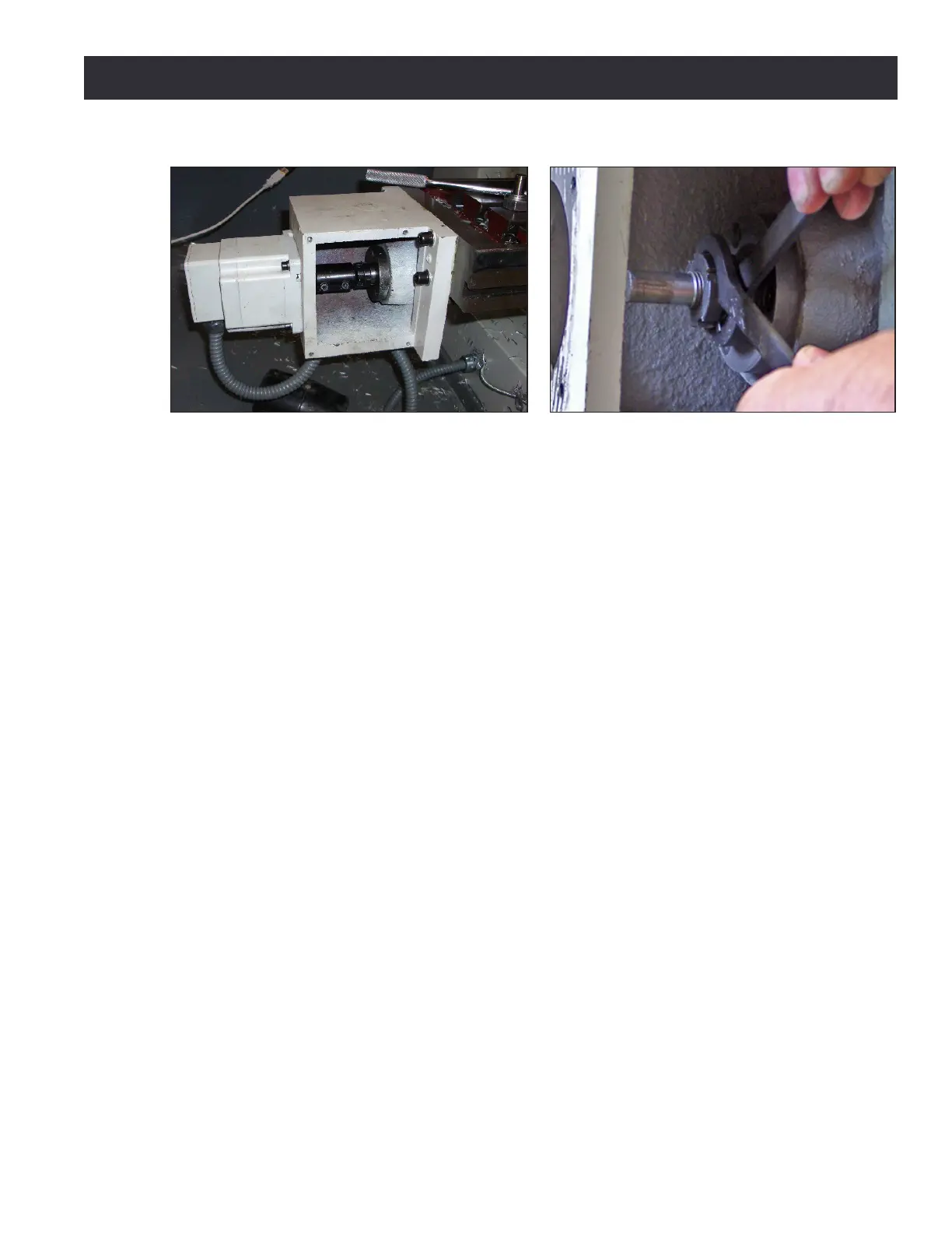
2. Remove X-axis motor mount cover plate (see Figure 9.8).
3. Loosen two screws clamping the coupling between the stepper motor sha and ball screw end.
4. Remove four cap screws holding the axis motor to the motor mount and remove axis motor.
Take care not to put any strain on the motor wires.
5. Insert a 1/2” diameter rod (included in AC Bearing Service Tool Kit, PN 35355) or drill blank
into the coupling. This will eecvely extend the ball screw sha outside of the motor mount.
6. Clamp a handwheel or vise grip on the end of the rod; this allows sensive feel for the torque
caused by the preload on the bearings. Rotaon should be smooth with a small percepble
drag; this corresponds to a medium preload of about 150 pounds. If the rotaon feels ght,
you have too much preload and will dramacally shorten the life of the bearings. If the rotaon
is free, you have lile or no preload and backlash will be excessive. This test should be done
with the lock nut ght.
7. Using kit’s spanner wrenches as shown Figure 9.9, adjust preload (refer to Adjustment
Procedure secon earlier in this chapter).
8. Re-mount box and motor; ensure that coupling is symmetrically ed to the motor sha and
the screw end and is fully ghtened (see Figure 9.9).
9.3.5 Geometry Adjustment of Precision Mating Surfaces
All precision mang surfaces are pinned together with tapered dowels during assembly at the
factory. The pinned connecon ensures that factory alignment is maintained in the event of a tool
crash. Each dowel pin has a small metric threaded hole in the center that can be used to extract the
dowel should it be required for disassembly.
Under typical usage, no adjustment of pinned connecons should be necessary. In the event of a
hard crash, shims can be used to make minor alignment adjustments between pinned components.
Small adjustments (less than .010”) will generally not require a full disassembly of the pinned
connecon. In these cases, the alignment dowels can be le in place, and the shims can be inserted
into a small opening created by loosening the bolted connecons.
Figure 9.8 Figure 9.9