Chapter 5
48
UM10350_PCNC770_Manual_0916A
Intro to PathPilot
5.1.4.2 Setting Tool Length Offset by Touching Off Workpiece
This secon assumes that you have already
set the work oset Z zero to the top surface
of the part using the steps in Seng Work
Oset by Touching o Workpiece. The
steps below describe an alternave to
using the TTS height gauge. If you have the
8” Digital Height Gauge (PN 31761), it may
be easier to measure the tools oine and
enter their lengths directly into the tool
table on the Osets tab.
To touch o the tool osets:
1. The 3/8” tool used to set X and Y work
osets earlier in this chapter should
sll be in the spindle; this is Tool 1.
Type 1 in the tool DRO and click the
M6 G43 buon to tell the mill that
you have changed tools and want to
apply the tool length oset.
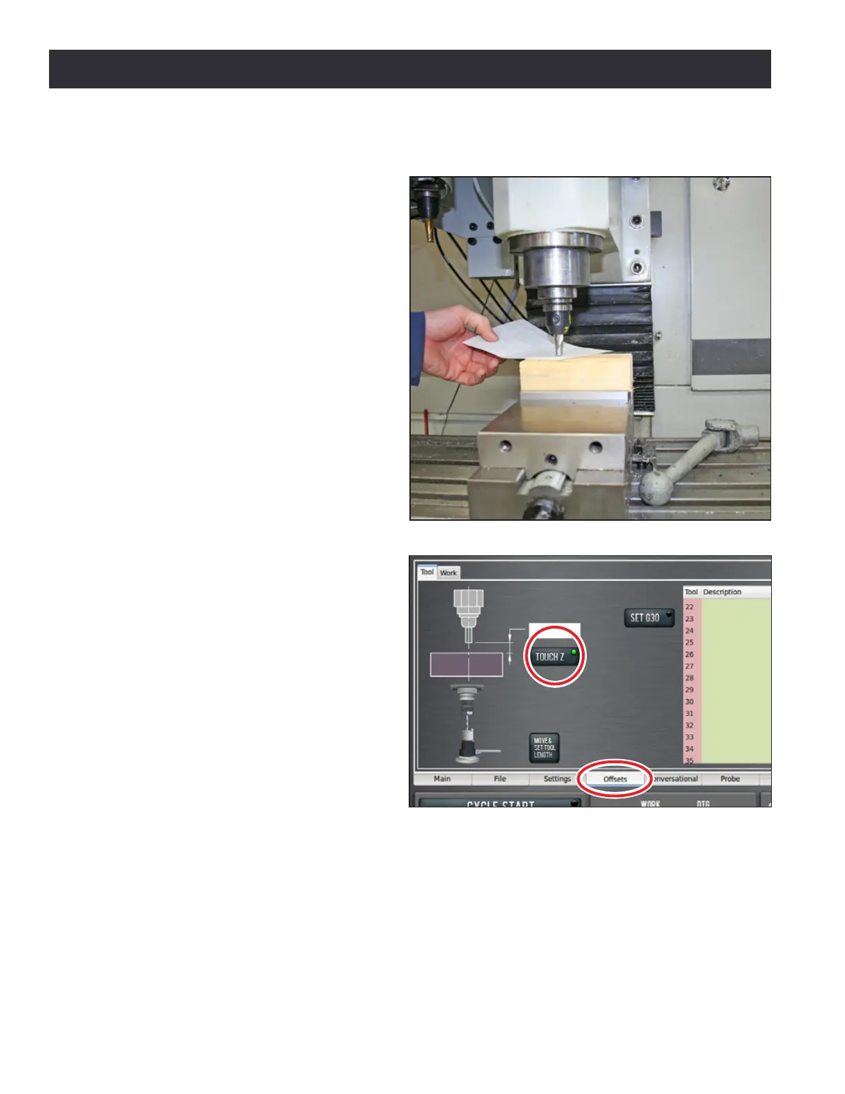
2. Jog the mill down so that the tool
just touches the top of the 2” x 4”
(see Figure 5.7).
3. On the Osets tab, enter 0.0 in
the Touch DRO and click the Touch
Z buon (see Figure 5.8). If you
were not touching on the top of the
workpiece, but instead using a feeler
gauge or piece of paper between the
workpiece and the tool, you could
enter the thickness of the gauge
or paper in the Touch DRO before
clicking Touch Z to account for the
gauge thickness.
4. Look at the length value in the tool table for Tool 1. Verify that it is correct by measuring the
length of the tool from the spindle nose to the tool p with a ruler or calipers.
5. Enter the diameter of the tool in the tool table (see Figure 5.9) and press Enter.
NOTE: Fracons entered in these entry elds are converted to their decimal equivalents.
6. Put the 1/8” end mill tool holder into the spindle.
Figure 5.7
Figure 5.8