Chapter 3
27
UM10350_PCNC770_Manual_0916A
Installation
7. Ensure coupling is centrally posioned between motor sha and machined end of Ball Screw;
ghten cap screws on coupling.
8. Tighten cap screws holding motor to motor mount securely.
3.3.5 Lift and Move Mill
WARNING! Transport and Li Hazard: The transport, liing, and moving of PCNC mill should be
done by qualied professionals. Failure to do so may result in mill damage, serious injury or death.
3.3.5.1 Remove Mill from Pallet
The mill is secured to the shipping pallet with four bolts. Before aempng to li mill, use wrench to
remove nuts holding mill to pallet. This allows mill to be separated from shipping pallet when liing.
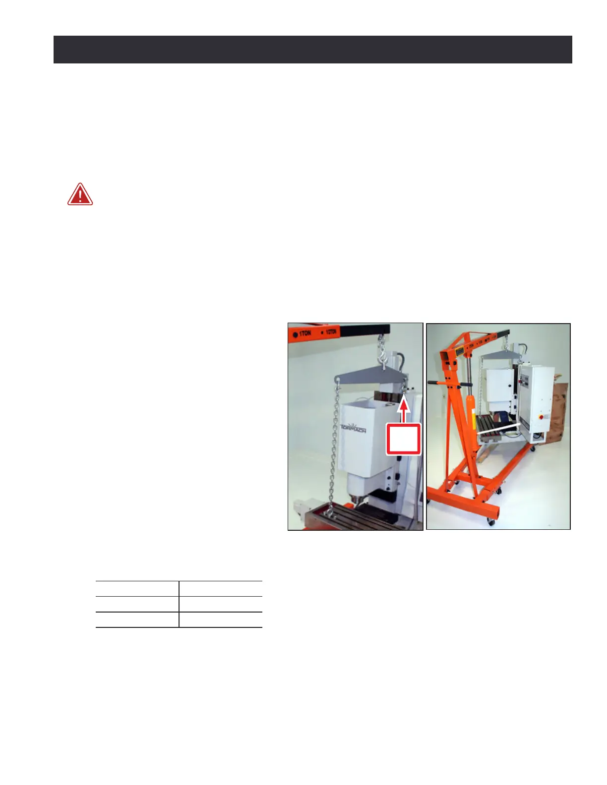
3.3.5.2 Lifting Bar Kit
The preferred method for liing the
mill is from above, using the Liing
Bar Kit (PN 31446), as shown in Figure
3.5; use this method with either a
forkli or engine hoist. The single
Eye Bolt on the top of the column is
suitable for liing the enre weight
of the mill. However, it is recommend
that the Liing Bar Kit be used (see
Figure 3.5 and Figure 3.6). Refer to
documentaon that ships with Liing
Bar Kit for more informaon on use.
Do not aempt to li mill from above
using any other method. If using an
engine hoist, refer to the following
table to determine the minimum
distance necessary to straddle stand
between hoist legs.
Machine Measurement
PCNC 1100 37”
PCNC 770 29”
3.3.5.3 Lifting from Below
It is also possible to li the mill from below by inserng steel bars into two sets of opposing 7/8”
diameter holes located in the machine base. The bars must be a minimum of 32” in length and
should be made of solid steel. Do not use hollow pipe to li mill.
Figure 3.5
Figure 3.6
Eye
Bolt