Chapter 3
29
UM10350_PCNC770_Manual_0916A
Installation
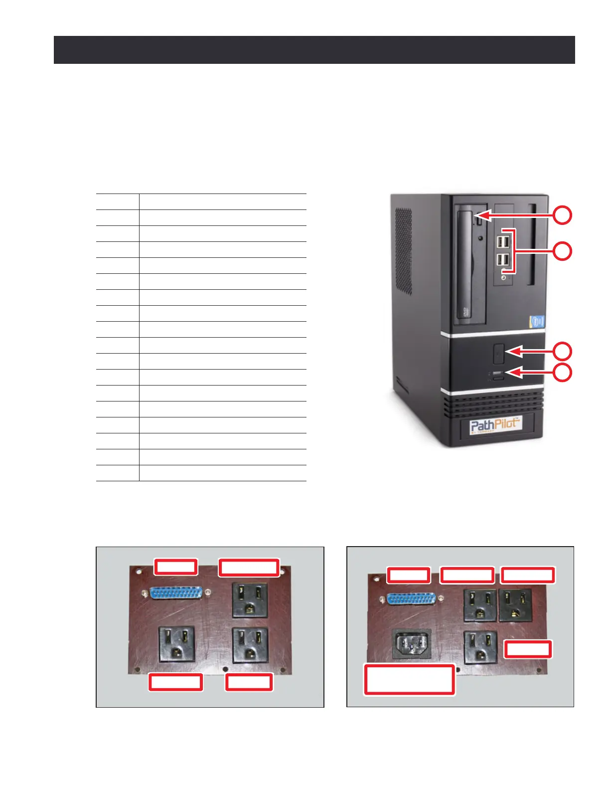
3.3.8 Install PathPilot Controller
Review the connecons on the front and rear of the PathPilot
®
controller as shown in Figures 3.9
and 3.12. When all the connecons are complete, place controller in the controller compartment
located on the right side of the stand.
PathPilot Controller (PN 35286)
Item # Connection or Component
1 Power/Reset with LED
2 USB Connectors (4)
3 Optical Drive
4 Hard Drive LED
5 PS/2 Connector
6 USB Connectors (2)
7 DVI Connector
8 VGA Connector
9 DP*
10 HDMI*
11 Blue USB Connectors (4)
12 Ethernet Connector
13 Audio Connections*
14 Mill Interface Port
15 Voltage Setting Switch
16 PCI Expansion Slot
17 AC Power Connector
*NOTE: Do not use these controller features.
Figure 3.9
3
1
4
2
Figure 3.11
Secondary Power
Input
Monitor
Controller
Coolant
DB-25
PCNC 1100 Power Connection Panel
Figure 3.10
DB-25
Monitor
Controller
Coolant
PCNC 770 Power Connection Panel