Chapter 3
30
UM10350_PCNC770_Manual_0916A
Installation
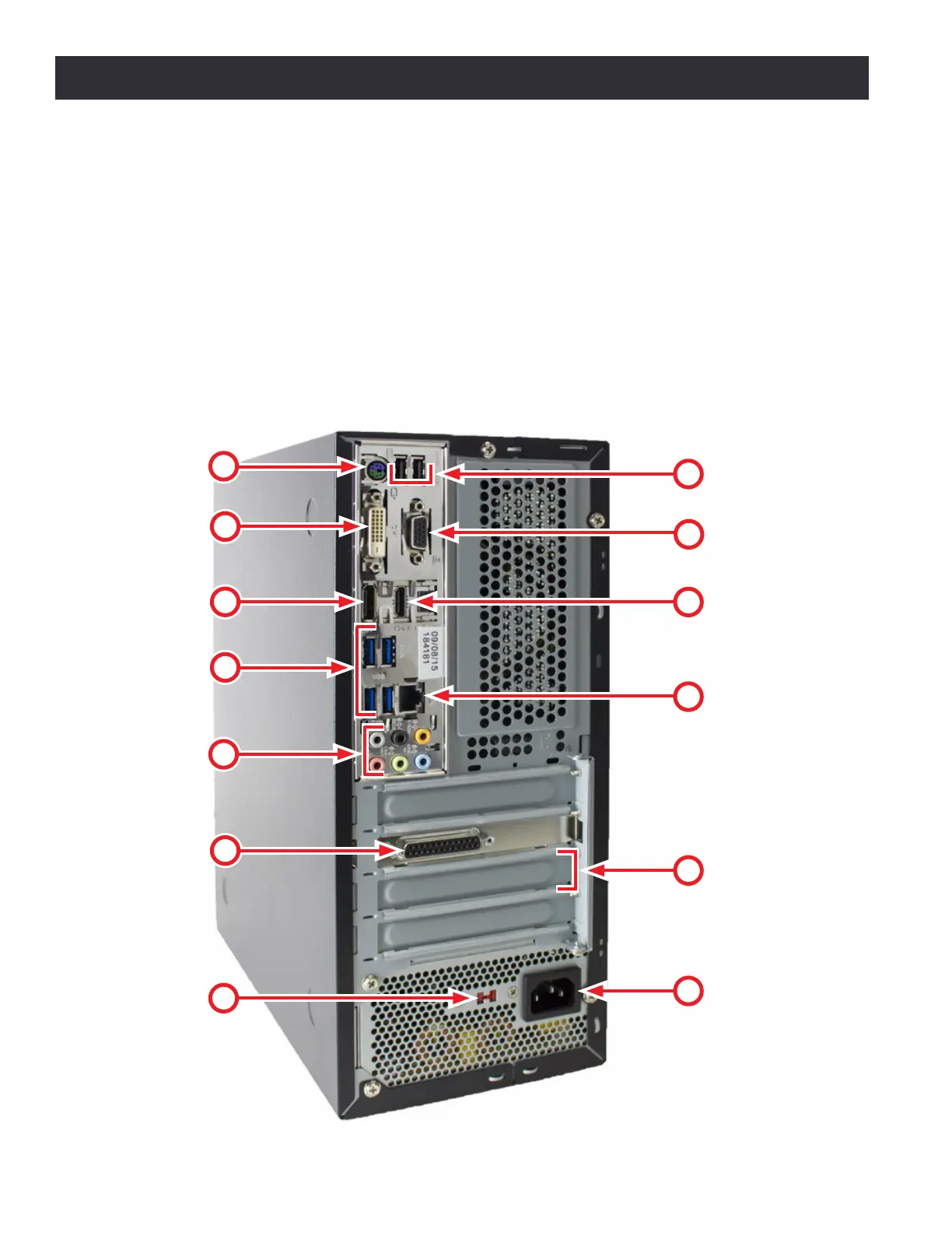
Set up and connect the PathPilot controller as follows:
1. Conrm Voltage Seng Switch (#15) is set to proper voltage for the geographic locaon before connecng
power. Plug the power cord into the AC Power Connector (#17) on the PathPilot controller.
2. Connect ferrite end of DB-25 interface cable to Mill Interface Port (#14).
3. Plug controller, monitor, loose end of DB-25 interface cable (included), and secondary power cord (included
with PCNC 1100 only) into Power Connecon Panel (see Figure 3.10 and Figure 3.11), located under the
electrical cabinet.
4. Connect monitor to either the DVI Connector (#7) or the VGA Connector (#8).
5. Connect keyboard, oponal jog shule, oponal ATC, and oponal USB I/O board to Blue USB Connectors (#11).
6. Connect other USB devices to any USB Connectors (#2, #6, or #11); do not use wireless keyboard/mouse.
Figure 3.12
6
7
8
9
10
11
12
13
14
15
16
17
5