Chapter 11
226
UM10350_PCNC770_Manual_0916A
Diagrams and Parts List
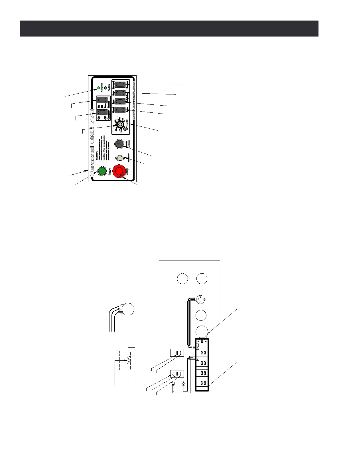
11.6 Operator Panel
OPERATOR PANEL with components identification
(assembly part number 32098)
1
3
2
POT1
POT1
1
3
2
DETAILS: POT1 CONNECTIONS
SCHEMATIC (THEORY)
PHYSICAL
BACK SIDE VIEW
OPERATOR PANEL with wire identification
BACK SIDE
30463 Push Button PB2
30462 Estop Button PB1
32006 Switch, On-O-On
32007 Switch On-O
32007 Switch On-O
32007 Switch On-O
32008 Switch (on)-O Momentary
32008 Switch (on)-O Momentary
30179 Potentiometer
30181 Knob
31039 Accessory/Probe
Port Assembly
30464 Key Switch w/Keys
31040 LED Assembly
32099 Front Panel Mounting Plate
32089 PCB for Spindle Control
POT1
122
120
126 (J5-1)
120
124
POT1 (PN 31041)
1
2
1
2
3
1
2
3
4
SW 1
Fwd/Rev
SW3
Start
SW4
Auto/Man
J11
J12
J3
1
2
1
2
1
2
1
2
3
4
SW2
Stop
CONNECTION BOARD
32089
DIN CONNECTOR ASSY
31039
LED ASSY
P/N 31040