Chapter 8
157
UM10350_PCNC770_Manual_0916A
Accessories
Aer calibraon, mark the spindle pulley with a marker or paint pen at a locaon that corresponds
to the angular posion of the probe cord. This allows the probe to be removed and replaced in the
exact spindle orientaon it was calibrated for — and eliminate error stackup.
8.9.3.2 Measuring Probe Tip Diameter
Use a micrometer to directly measure probe p diameter. Enter this data into tool table for Tool #99.
8.9.4 Tool Setter
The Electronic Tool Seer (ETS) can be interfaced to
the accessory port of either the PCNC 770 mill or the
PCNC 1100 mill (see Figure 8.25).
PN Description
31875 Tool Setter
This device can be used for two funcons:
• Precision work seng (Z-plane only)
• Precision tool seng
8.9.4.1 Tool Setter Trigger Height
The trigger height of the ETS is 80 mm (3.1496”). This is the default value in the ETS Height DRO on
the Probe/ETS Setup tab in PathPilot
®
(see Figure 8.23). If using a non-Tormach tool seer, consult
the manufacturer for trigger height and enter this value in the ETS Height DRO. If in G20 (imperial
units) enter the height in inches; if in G21 (metric units) enter the height in millimeters.
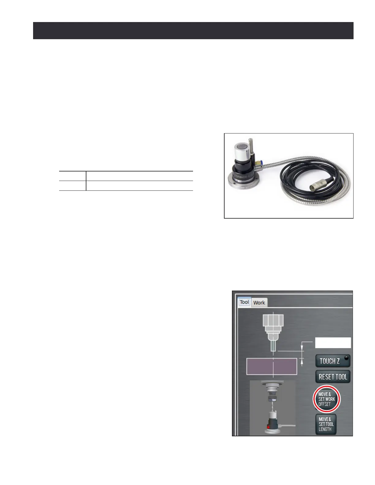
Using Tool Seer to Set Z Work Osets
Once trigger height of tool seer is established, it can
be used to assign dierent Z work osets as follows:
1. Click Osets tab, then Tool tab (see Figure 8.26).
2. Place tool seer on surface where work oset is
to be located (e.g., top of workpiece, top of vise,
or top of mill table).
3. Conrm desired work oset (i.e., G54, G55, G56)
is acve in the control.
4. Conrm that tool number T DRO corresponds to
tool currently in spindle.
5. Click Move & Set Work Oset (see Figure 8.26).
Figure 8.26
Figure 8.25