Chapter 8
156
UM10350_PCNC770_Manual_0916A
Accessories
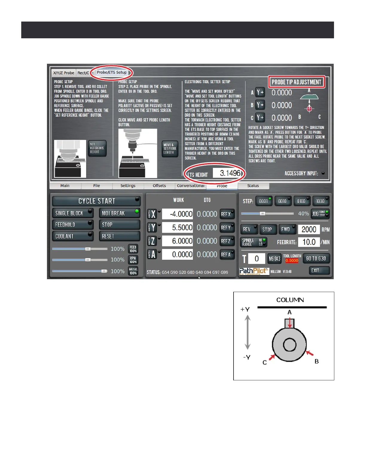
a. Orient the probe in the spindle so one of three
adjustment screws is opposite the machine column (see
Figure 8.24). Label this Screw A.
b. Press Y+ buon next to A.
c. Rotate spindle 120° clockwise (as viewed from above
the probe) so next screw is opposite machine column.
Press Y+ buon next to B.
d. Similarly, rotate spindle a third me unl nal screw
is opposite machine column. Press Y+ buon next to C.
e. Tighten the screw corresponding to the largest DRO
value (A, B, or C). Alternavely, if the screw cannot be
ghtened, loosen the other two screws.
f. Iterate this process unl all DROs read the same value.
All screws should be ght.
Figure 8.24
Figure 8.23