Chapter 3
26
UM10350_PCNC770_Manual_0916A
Installation
3.3.2 Remove Tool Tray (PCNC 1100 only)
Carefully remove the Tool Tray from the pallet and set aside for installaon later (see Figure 3.7).
3.3.3 Remove Accessory Tool Box
A wooden Tool Box is nailed to the pallet (see Figure 3.2). This box contains tools that are required
for installaon. Carefully remove box from pallet using pry bar.
NOTE: The Spindle Lockout Key – used to lock or unlock the spindle – is located in the Tool Box. The spindle
with not rotate without the key inserted in the Operator Panel locaon shown in Figure 3.13.
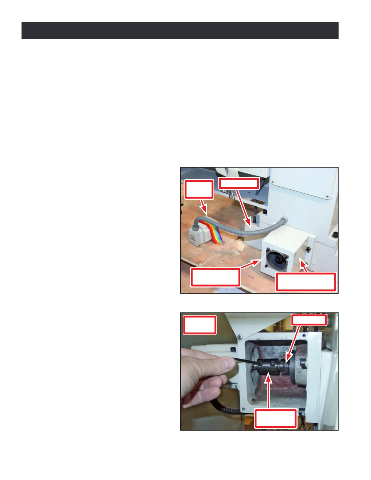
3.3.4 Assembling Y-Axis (PCNC 1100 only)
The PCNC 1100 is supplied with the Y-axis
Motor mechanically disconnected; install
it before aempng to remove mill from
pallet (see Figures 3.3 and 3.4).
IMPORTANT! Damage to mill may occur if Y-axis
Motor weight is supported by motor wires.
1. Unstrap Y-axis Motor from pallet
(see Figure 3.3).
2. Remove Y-axis Motor Mount Cover
Plate from Y-axis Motor Mount (see
Figure 3.3).
3. Using 4 mm hex wrench (included),
loosen two Motor Sha Coupling
screws on end of Ball Screw (see
Figure 3.4).
4. Remove four cap head screws from
Y-axis Motor Mount (see Figure 3.3).
NOTE: Remove any paint around motor mount
that could cause misalignment.
5. Use four cap head screws from step
4 to mount Y-axis Motor onto Y-axis
Motor Mount. Wire loom should
face toward oor (see Figure 3.3).
Make sure motor and motor mount
faces are ush.
6. Aer ghtening four cap head
screws, back them o one-quarter
turn so motor is free to self align.
Figure 3.4
Coupling
Box
Motor Shaft
Coupling
Ball Screw
Figure 3.3
Y-axis Motor
Mount
Wire Loom
Y-axis Motor Mount
Cover Plate
Y-axis
Motor