Chapter 3
33
UM10350_PCNC770_Manual_0916A
Installation
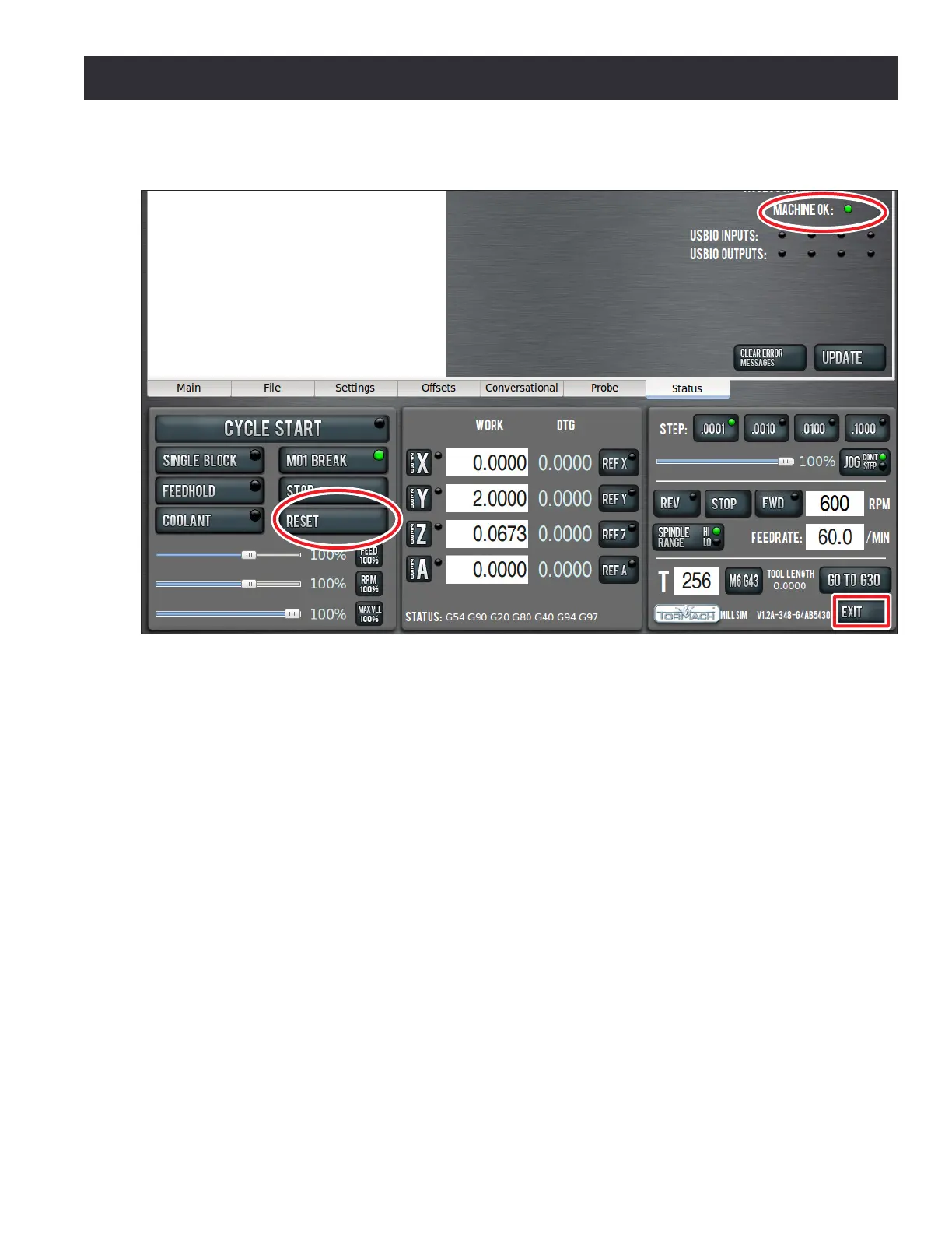
Reset
Click the PathPilot interface’s Reset buon to establish communicaons between controller and mill
(see Figure 3.17). The Controller LED on the operator panel indicates when communicaon has been
established.
Main Disconnect
The Main Disconnect switch, located on the right side of the electrical cabinet, is used to power the
mill o and on (see Figure 3.13). When the Main Disconnect is switched to power O, it disconnects
the primary supply power to the mill. On the PCNC 1100, when the Main Disconnect is switched
to power O, it also disconnects the secondary supply power (to controller, monitor, and coolant
outlets) from the Power Connecon Panel (see Figure 3.10).
3.6 Power Off/Power On Procedure
IMPORTANT! Do not power on motors and drives via the green Start buon before powering on the
controller that oversees their operaon. Make sure that the controller is on and the PathPilot interface is
loaded before powering on the mill. Likewise, make sure to depress the red E-stop before powering o the
controller using the Exit buon on the PathPilot interface (see Figure 3.17). Conrm that the mill powers
o and on correctly using the procedure detailed in this secon.
PathPilot Interface
Figure 3.17