Chapter 10
184
UM10350_PCNC770_Manual_0916A
Troubleshooting
10.5.1.2 Details of Power Distribution Subsystem
The PCNC mill is powered by an operator provided nominal 120/1/60 (120 V single phase, 60 HZ) 20
amp, 3-wire electrical circuit in North America. If only 220 VAC is available, a step down transformer
is required. Operaonal PCNC mill voltage range is from 115 VAC to 135 VAC.
NOTE: The system funcons down to 100 VAC, but operang below 115 VAC diminishes torque at high
spindle speeds.
The two current carrying conductors of this supply are connected to the Main Disconnect, located
on the right side of the electrical cabinet. When the Main Disconnect is in the o posion, no
power is supplied to the mill. Find the relevant poron of the electrical schemac highlighted in
Figure 10.5. For more detail, view electrical schemac inside back cover.
One leg of the two current carrying conductors is grounded. A third wire ground must also be
provided. The ungrounded leg of this supply is connected to a third pole on the Main Disconnect
described above. Running the circuit in this manner allows the coolant pump outlet to be controlled
either automacally by the mill controller or manually depending on the posion of the coolant
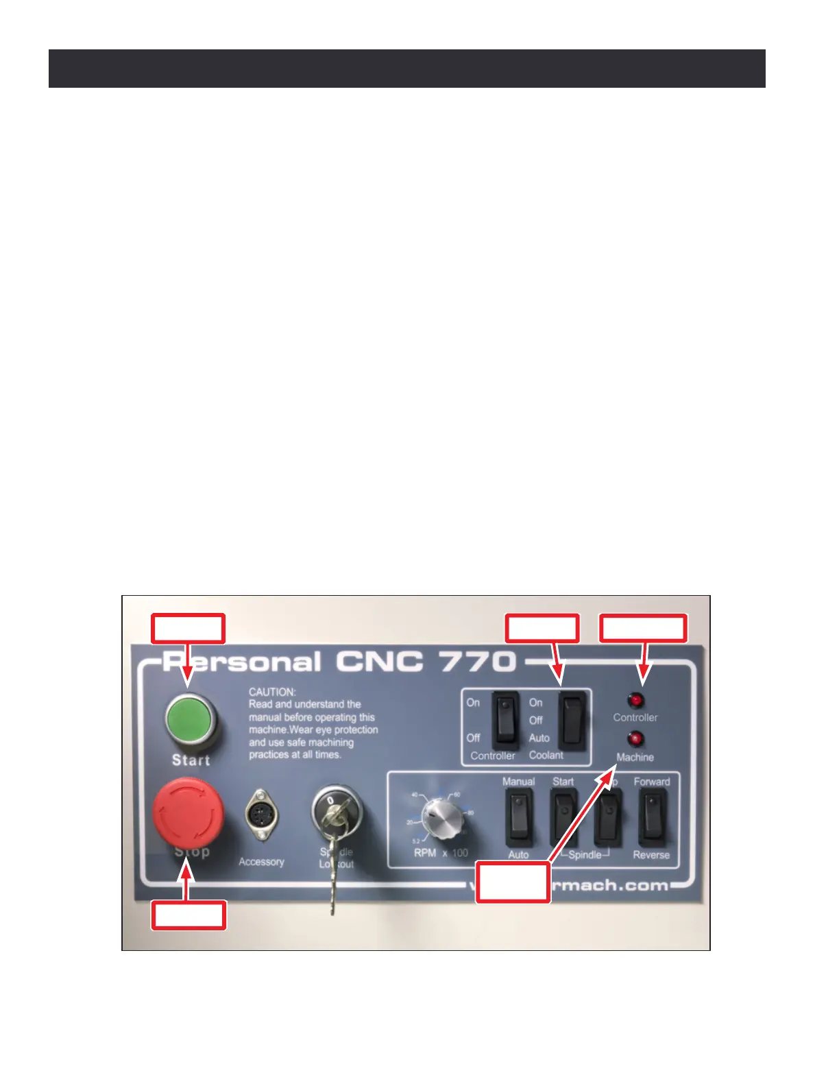
switch, SW5, on the Operator Panel (see Figure 10.7). The circuit also provides power to two outlets
which can be used for the controller and monitor. These outlets are controlled by SW6, labeled
Controller, on the Operator Panel. This allows turning o of the controller when mill power is sll
on. Turning the Main Disconnect to the o posion powers o the coolant and controller outlets.
Figure 10.7
Start
E-stop
Machine
LED
Coolant
Controller
Operator Panel