Chapter 4
41
UM10350_PCNC770_Manual_0916A
Operation
4.4.2 Automated Spindle Control Via PathPilot Interface
To control the spindle via the PathPilot interface, switch the spindle to Auto on the Operator Panel
(see Figure 4.1).
Ensure the Spindle Range buon’s LED light (see Figure
4.5) correctly corresponds to the spindle belt posion,
either Hi or Lo; click to toggle between the two posions.
For more informaon on the procedure to change belt
posion, refer to Changing Spindle Speed Range secon
later in this chapter.
NOTE: A mismatch between the Spindle Range buon and actual spindle belt posion will result in the
commanded speed being dierent from the indicated RPMs. See table below for available speed ranges
for each spindle opon.
To specify spindle RPMs, click the DRO. Using the keyboard, type the desired RPM and press Enter.
• Click FWD to run the spindle clockwise
• Click REV to run the spindle counterclockwise
• Click Stop to stop the spindle
4.4.3 Changing Spindle Speed Range
Each PCNC mill has two speed ranges as outlined in the table below.
Low High
PCNC 1100 100-2000 250-5140
PCNC 770 175-3250 525-10,020
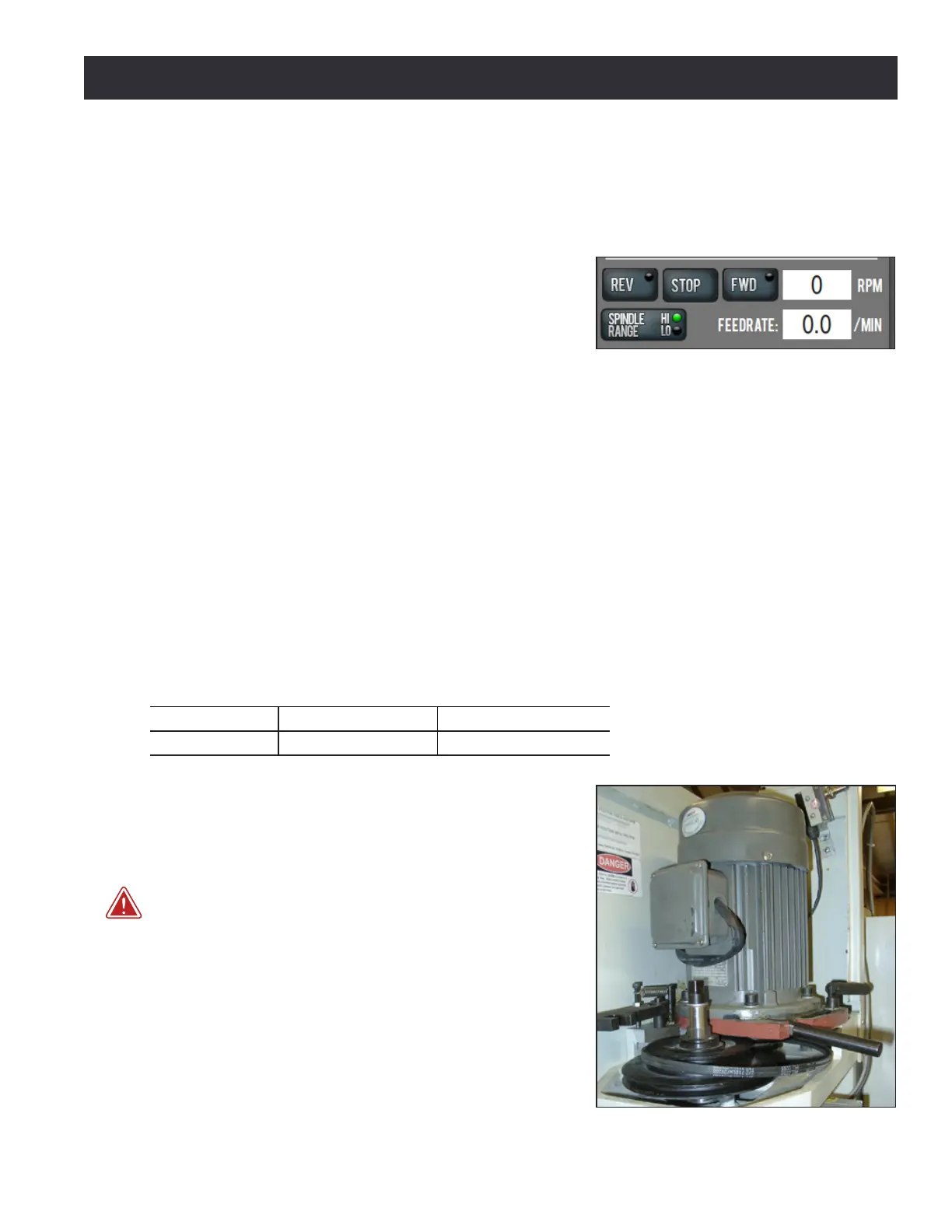
The range change is performed by moving the spindle
belt from the top pair of pulleys (high speed range) to
the lower pair of pulleys (low speed range). To change
belt posion:
WARNING! Electrical Shock Hazard: Be sure to power o
machine before making any electrical modicaons. Failure to
do so may result in serious injury or death.
1. Power o mill according to power o/on procedure
detailed in chapter 3, Installaon.
2. Open spindle door; use the rear handle to unlock
motor mounng plate and pull motor forward. The
belt will slacken and can be moved from one pulley
to another (see Figure 4.6).
Figure 4.6
Figure 4.5