Chapter 3
35
UM10350_PCNC770_Manual_0916A
Installation
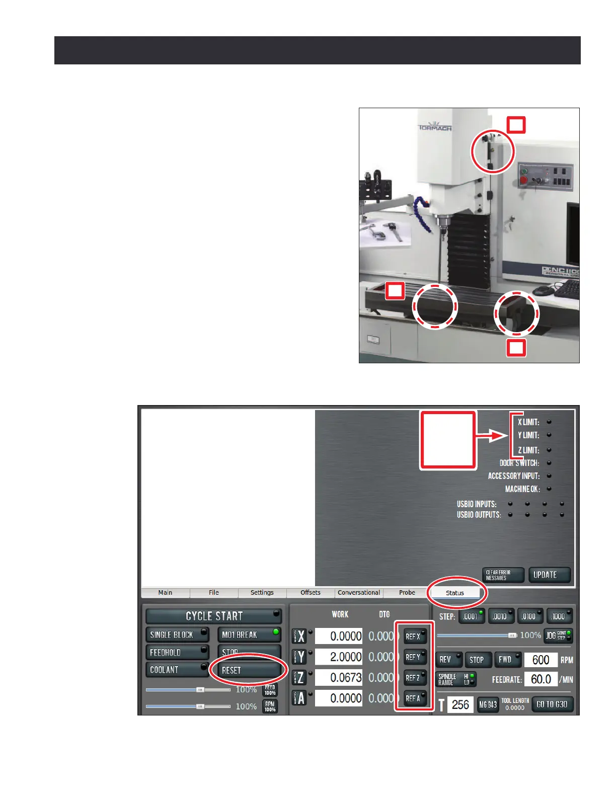
3.7.2 Verify Limit Switch Function
Limit switches prevent the mill from exceeding
its travel limits and provide a reference locaon
during the mill homing procedure. There are three
limit switches, one for each axis of moon (X, Y,
and Z). Refer to Figure 3.18 for the locaon of each
limit switch. If a limit switch is triggered, the mill is
placed in a reset state. Verify proper limit switch
funcon as follows:
1. On the PathPilot interface, click the Status
tab (see Figure 3.19).
2. Manually depress X, Y, and Z limit switches
by hand (see Figure 3.18).
3. Verify that the corresponding limit switch
LED light illuminates on the Status screen
(see Figure 3.19).
4. Aer verifying limit switch funcon, click the
ashing Reset buon (see Figure 3.19).
Figure 3.18
X
Y
Z
Figure 3.19
Limit
Switch
LED
Lights