Chapter 6
57
UM10350_PCNC770_Manual_0916A
PathPilot Interface
When the mill is at rest, these readouts are also operator entry elds. Change the current work
oset posion by clicking in the DRO eld, which illuminates. Type a number, for example 4.0, and
click Enter on keyboard. Press the Esc key to return to the original value.
This technique is used for seng any DRO. Remember to click Enter aer any DRO change. If you
forget and just click on another DRO, any value you have just entered is discarded. This is designed
to avoid accidental changes.
For convenience, the Zero buon to the le of the axis DROs can be used to set the current work
oset posion for that axis to 0.000.
DTG (Distance to Go) – Just to the right of the axis DROs are the DTG (see Figure 6.2) or Distance
to Go labels (light blue) that are read-only and display the distance remaining in any single move.
If you feedhold the mill in the middle of a move, or turn the Maxvel or Feedrate overrides to 0
percent, these labels display the distance le in the commanded move. These labels are useful
when proving out a part.
Ref Axes Buons – Ref X, Ref Y, Ref Z, and Ref A buons reference the axes to their home switch
locaons. This must be done aer power on and before running a part program or using MDI
commands. The axes may be referenced simultaneously, though it is common pracce to reference
the Z-axis rst to clear the spindle or tool from the area of the workpiece or vise. When referenced,
the LED is illuminated.
Status – The Status line displays the currently acve G-code modalies and the acve tool. A more
detailed descripon of these acve G-codes is provided on the Sengs tab.
Jog Acve LEDs – Between the (Zero) Axis and DROs are LEDs. If the mill is equipped with an oponal
Jog Shule (PN 30616), the acve jog axis is indicated by an illuminated LED (see Figure 6.3).
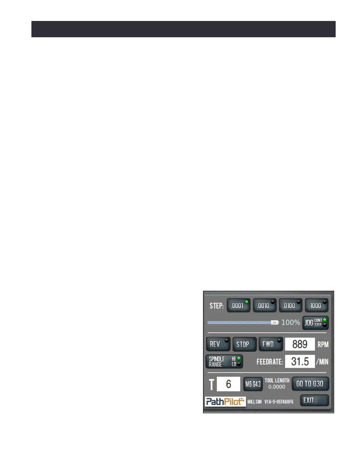
6.2.3 Manual Control Group
The Manual Control Group's buons, slider, and
DROs allow the operator to perform tasks related
to manual control of the mill, including jogging
the mill axes, changing the current tool number,
feed rate, or spindle speed, and starng or
stopping the spindle (see Figure 6.4).
Figure 6.4