Chapter 10
187
UM10350_PCNC770_Manual_0916A
Troubleshooting
10.5.2.1 Details of Control Power Subsystem
The control power circuit is that circuit which is powered on when in a ready to run state, and which
powers o when the red E-stop is in the depressed posion. The circuit does not power on unl the
red E-stop is released and the green Start buon is momentarily depressed. When control power is
o, the mill is in an o state, however some components in the electrical cabinet are sll powered
on including the main fuses FU1, FU3 and FU6, and wires 102 and 103 on the red E-stop and green
Start buon. In addion, the following wires have voltage present even if the mill is in the O state:
• Wire 140 going to the C2 contactor
• Wire 129 going to the C1 contactor
• Main control board and switches for coolant (SW5) and controller power (SW6)
• Depending on the posion of SW5 and SW6, there could be voltage at the power outlets
mounted to the boom of the electrical cabinet on wires 122 and 124
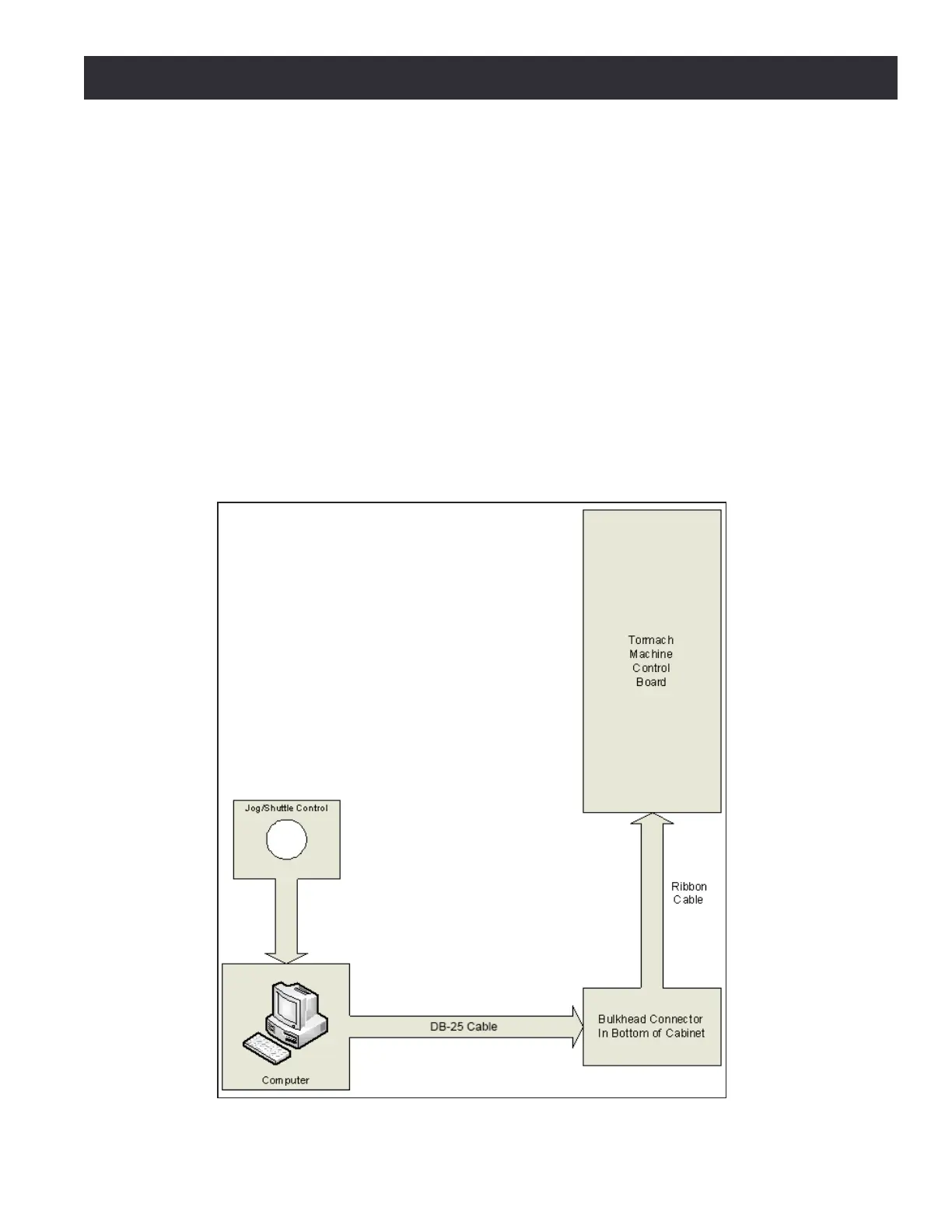
Figure 10.10