Chapter 9
168
UM10350_PCNC770_Manual_0916A
Maintenance
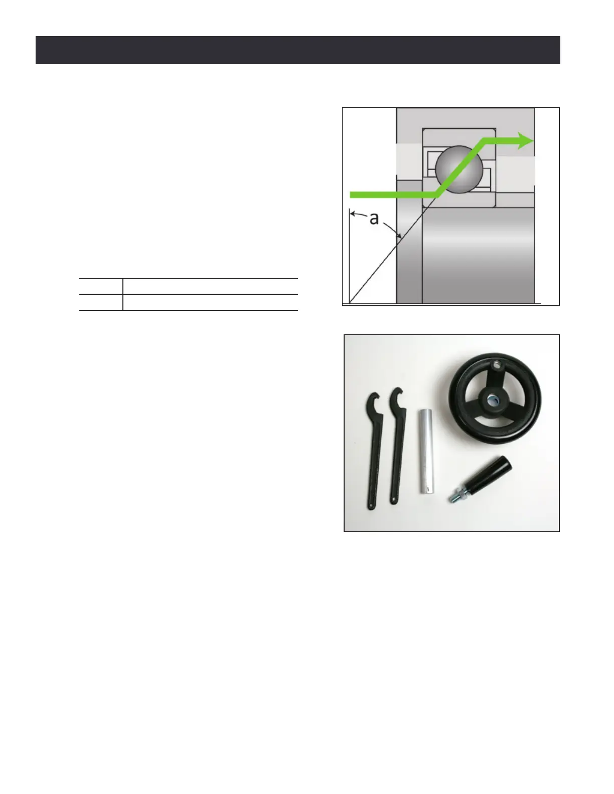
Figure 9.6 shows how the force of preload is
transmied through the bearings, from the inner
race to the outer race. In a preload pair, this force
is then transmied back to the inner race by an
opposed bearing. It should be apparent that the
correct orientaon of the angular contact bearing is
crical to the operaon.
9.3.4.2 Adjustment Procedure
To adjust the angular contact bearing pair preload,
the following kit is required (see Figure 9.7):
PN Description
35355 AC Bearing Service Tool Kit
There are two nuts: the adjustment nut and the
lock nut. The nut nearer the bearing housing is the
adjustment nut, and the one nearer the axis motor
is the lock nut (see Figure 9.5).
NOTE: When working on the Z-axis, remove any tooling
from the spindle and support the head by resng the
spindle nose on a block of wood.
1. Loosen the lock nut and back it o about two
turns.
2. Hold the ball screw to prevent it from rotang
with a pair of pliers on the coupling and ghten
the adjustment nut unl there is slightly more
backlash than you ulmately want to achieve.
Tightening the lock nut will slightly increase
the bearing preload.
9.3.4.3 Determining Proper Angular Contact Bearing Preload
To properly esmate the torque needed to overcome angular contact bearing fricon, the bearings
must be isolated from the stepper motor detent torque. Use the following procedure:
1. For adjusng the X-axis, posion the table near the right hand end of its travel (i.e., X near to
zero). This ensures that the bearing is near to the ball nut to minimize bending of the screw
during tests.
Figure 9.6
Figure 9.7