Chapter 5
47
UM10350_PCNC770_Manual_0916A
Intro to PathPilot
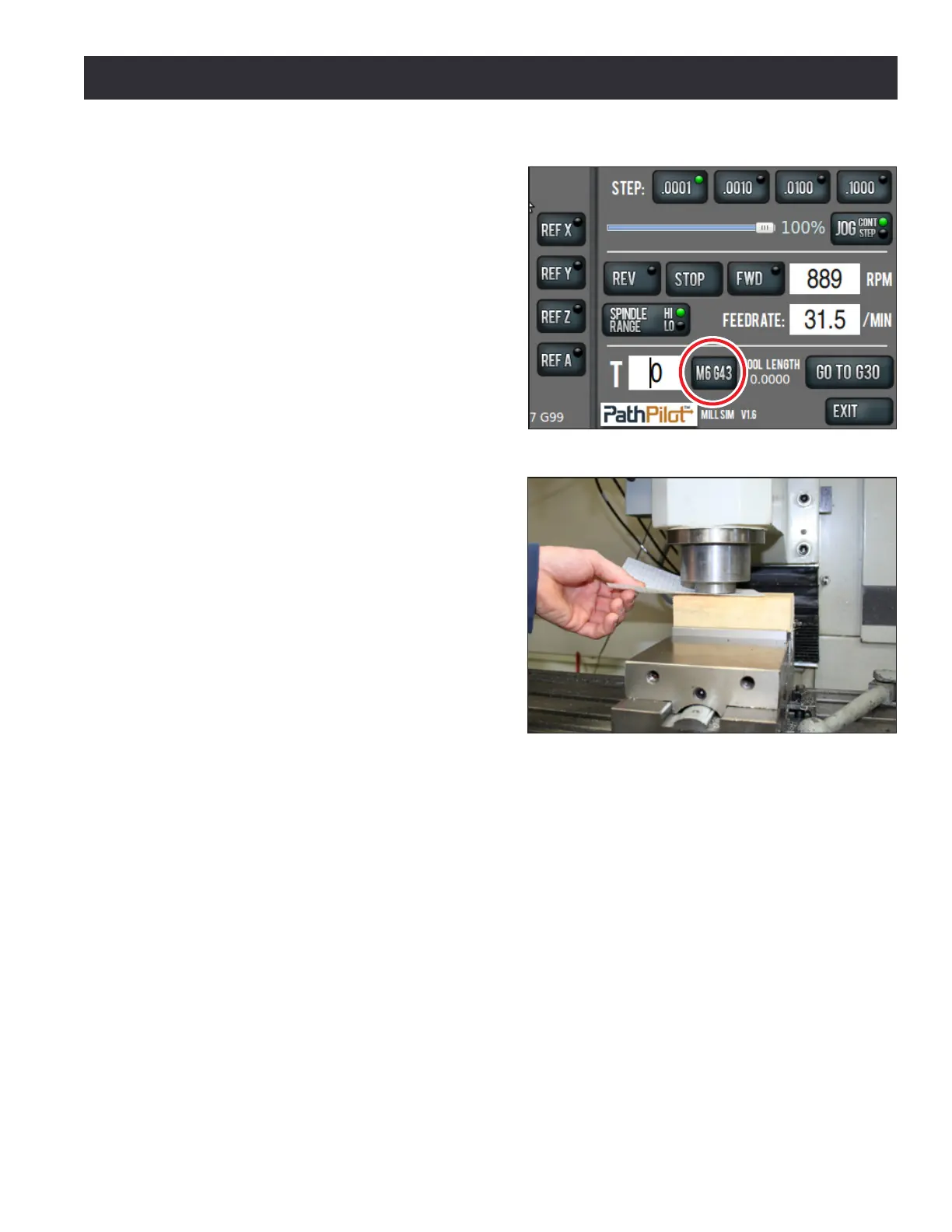
2. Type 0 in the tool DRO and press the M6
G43 buon to tell the PathPilot operang
system that we are changing tools and
applying a tool length oset. Tool zero
represents an empty spindle, and there
is no oset to apply. We press the M6
G43 buon to make sure there is no tool
length oset applied before we set the
work oset (see Figure 5.5).
3. Place a piece of scrap 2” x 4” in vise. Make
sure that the top of 2” x 4” is at least 1/4”
above the top of the vise jaws.
4. Place a piece of paper on the 2” x 4” and
jog the spindle down carefully unl the
spindle nose just makes contact with the
top of the 2” x 4”. You will be able to feel
when the paper is pinched (see Figure 5.6).
5. Press the Zero Z buon to set the work
oset Z to zero.
NOTE: This is just like typing 0.0 into the Z DRO and
pressing Enter. To account for the thickness of the
paper used in touching o the work oset, you could
type 0.003 in the Z DRO and press Enter.
Seng the X and Y Work Osets
Common posions for the X and Y part zeros are:
• The back le of the workpiece
• The center of the workpiece
• A feature (i.e., a hole or a boss) that already exists on the workpiece
For the rst part tutorial, we will use the X/Y center of the workpiece as the zero point. To set the X
and Y work osets for this part:
1. Using a straight edge, draw two lines on the 2” x 4” from corner to corner, creang an X in the
center of the workpiece.
2. Put the tool holder with the 3/8” end mill in it into the spindle.
3. Jog the mill so that the 3/8” end mill is approximately centered over the X on the workpeice.
4. Click the Zero X buon next to the X DRO.
5. Click the Zero Y buon next to the Y DRO.
Figure 5.6
Figure 5.5