Chapter 10
213
UM10350_PCNC770_Manual_0916A
Troubleshooting
Spindle Drive Subsystem Checklist
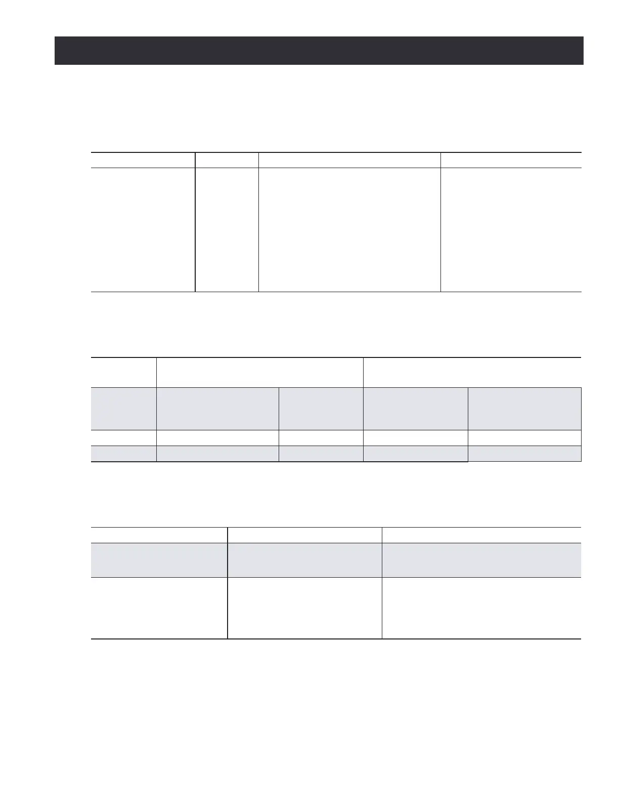
Table 5.1 (...continued)
Spindle will not turn on in manual or auto
Possible Cause Probability
Action to Identify Cause of Problem
Discussion
Defective motor Low
Power off the VFD using the key
switch. Wait 30 seconds and measure
resistance between the leads of the
motor which are wire numbers 400,
401, and 402. Remember to take a tare
reading with your meter. Refer to Using
the Digital Multimeter for Electrical Tests
earlier in this chapter.
Resistance should be in the
range of 2-4 Ω. 0 Ω would
indicate the winding is shorted
and >1M Ω would indicate the
winding is open, both cases
indicate a defective motor or
compromised wiring to the
motor from the VFD.
Spindle Drive Subsystem Checklist
Table 5.2a
Run and direction commands to drive
Command
From Card
Monitoring Points One Probe on Each Voltage Measured
Common wire number Wire number
Voltage when control
board command is on
Voltage when control
board command is
not on
Run J1-2 J1-3 20-28 VDC 0 VDC
Reverse J1-2 J1-6 0 VDC 20-28 VDC
Spindle Drive Subsystem Checklist
Table 5.2b
Main control board LED indicators for run and speed commands to drive
Mode Setting Indicator
Manual (front panel switch
turned to manual)
Spindle Start switch on Operator
Panel engaged.
Yellow LED D15 lights. Brightness is
proportional to speed.
Auto (front panel switch
turned to auto)
Spindle FWD button on controller
screen engaged.
Yellow LED D15 lights. Brightness is
proportional to speed. Green LED D10
lights and blinks at a rate proportional to
speed.