Chapter 10
215
UM10350_PCNC770_Manual_0916A
Troubleshooting
Power is supplied to the drive through a contactor that allows power to pass when the drive is
commanded to run by the operator. When the red E-stop is pressed, the Spindle Lockout Key S7 is
turned o, or when the spindle door LS5 is opened, contactor C2 de-energizes and interrupts power
to the VFD and prevents the motor from running.
NOTE: Aer a power o, the VFD will only power back on when rst commanded to spin in either manual
or auto mode. The VFD will not power on by pushing the green Start buon on the Operator Panel. Once
the VFD is powered on, it will stay on unl one of the above condions occurs.
Control signals are sent to the VFD from the main control board which gets commands from
the controller in automac mode or from the Operator Panel in manual mode. When Manual
is selected with the Spindle Mode switch, the Start and Spindle Stop switches, the Spindle
Forward/Reverse switch and the Spindle Speed Dial are used to control the spindle speed.
In the auto mode, none of these controls are funconal and all control for the spindle is provided by
the controller and mill operang system.
The control board provides a ve second contact closure pulse between wires 106 and 107 to cause
power to be applied to the drive. It also provides a run command, a direcon command, and an
analogue voltage in the range of 0-5 VDC to wires J1-1 (com) and J1-2 proporonal to desired speed.
See Table 5.1 and Table 5.2.
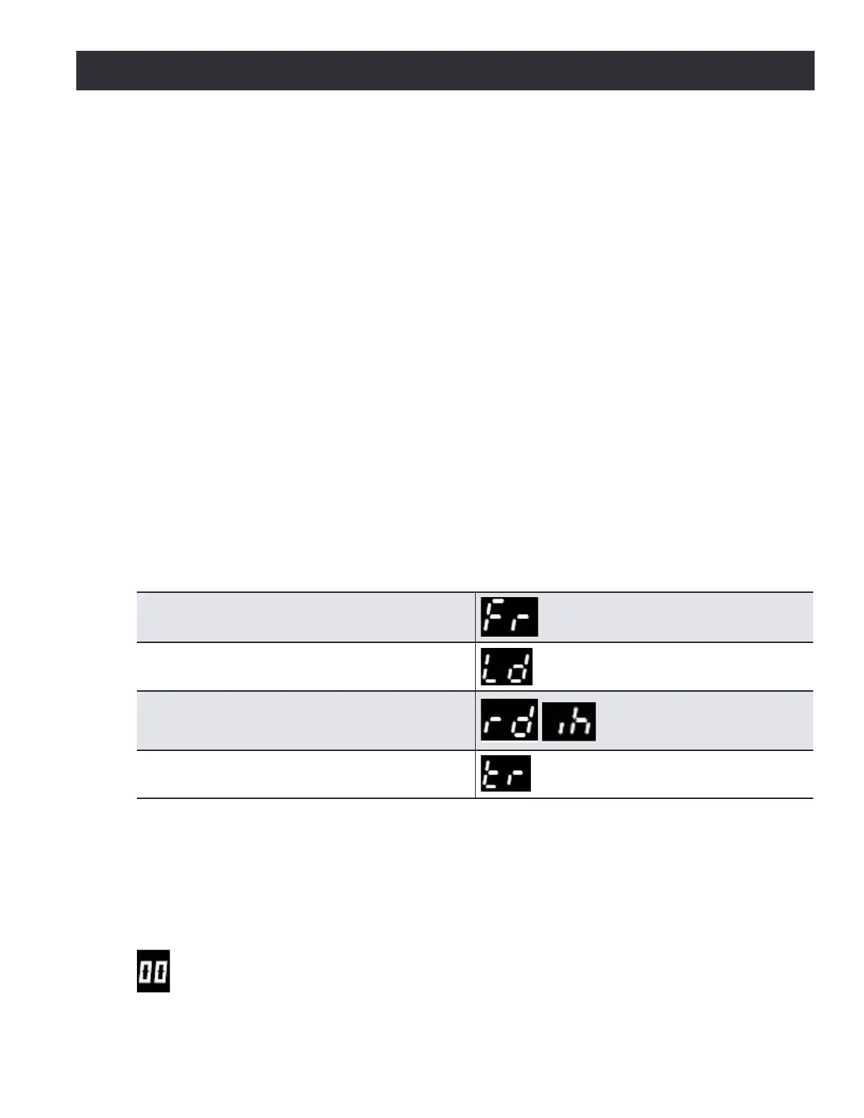
The display on the VFD provides valuable informaon for troubleshoong. The display will provide
diagnoscs which include:
Frequency output (proportional to speed. Range is
~7 HZ to 120 HZ).
Load percentage (load is proportional to the torque
the motor is outputting).
Status (rd for ready, ih for inhibit which will occur
when there is no jumper between terminals B2 and
B4 on the drive).
Fault information (tr for trip) and a code for the fault.
There are several VFD trip scenarios shown in Table 5.3.
The drive can also provide parameter informaon. This is informaon from the Tormach program
of the drive and is usually not important from an operator standpoint. If the drive is displaying this
sort of informaon, which always has two-digit numbers displayed on the le side of the display,
the operator must take acon to allow the drive to display the diagnosc informaon (above).