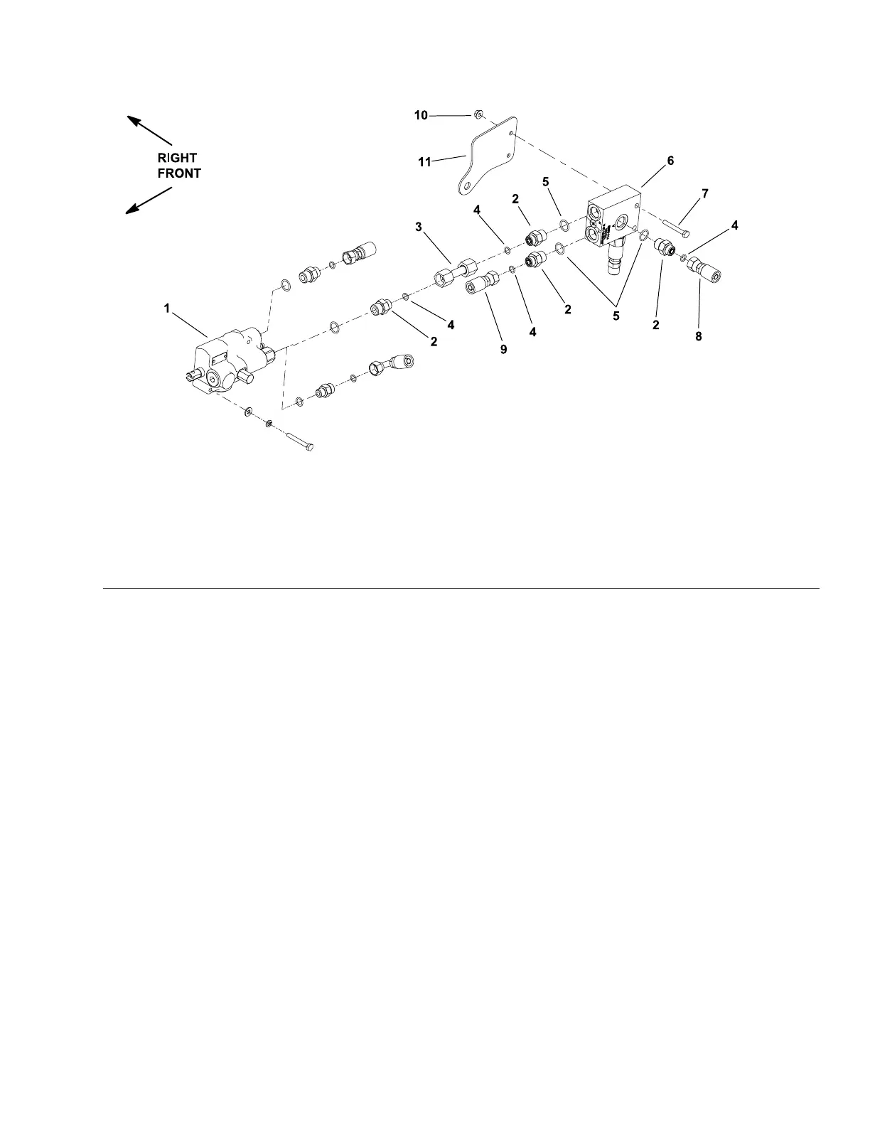
CounterbalanceValveManifold(MachineSerialNumbersbelow
311000000)(IfEquipped)
g230845
Figure106
1.Liftcontrolvalve5.O-Ring
9.Hydraulichose
2.Hydraulicadapter
6.Counterbalancemanifold10.Flangenut(2each)
3.Hydraulictube
7.Bolt(2each)
11.Mountingbracket
4.O-Ring
8.Hydraulichose
RemovingtheCounterbalanceValveManifold
1.Parkthemachineonalevelsurface,engagetheparkingbrake,lowerthe
cuttingdeck(orimplement),andshutofftheengine.Removethekeyfrom
thekeyswitch.
2.ReadtheGeneralPrecautionsforRemovingandInstallingtheHydraulic
SystemComponents(page5–77).
3.Removefueltankfrommachine;refertoRemovingtheFuelTank(page
3–10)orRemovingtheFuelT ank(page4–16).
4.Labelallhydraulicconnectionsforassemblypurposes.Cleanhydraulichose
endspriortodisconnectingthehosesfromcontrolmanifold.
5.Disconnecthoseconnectionsfromhydraulicttingsoncounterbalancevalve
manifold.Allowhosestodrainintoasuitablecontainer.
6.Putcapsorplugsondisconnectedhosesandttingstoprevent
contamination.
7.Remove2boltsand2angenutsthatsecuremanifoldtomachine.
8.Removemanifoldfromthemachine.
9.Removehydraulicttingsasnecessaryfromthemanifold.Discardall
removedO-rings.
Groundsmaster
®
3280-D/3320
Page5–133
HydraulicSystem:ServiceandRepairs
05138SLRevB
 Loading...


