InstallingtheHydraulicHoseandTube(O-RingFaceSealFitting)
1.Ensurethatallthethreads,thesealingsurfacesofthehose/tube,andthe
ttingarefreeofburrs,nicks,scratches,orunwantedmaterial.
2.Tohelppreventahydraulicleak,replacethefacesealO-ringwhenyouopen
theconnection.EnsurethattheO-ringisinstalledandcorrectlyseatedinthe
grooveofthetting.LightlylubricatetheO-ringwithcleanhydraulicuid.
g221221
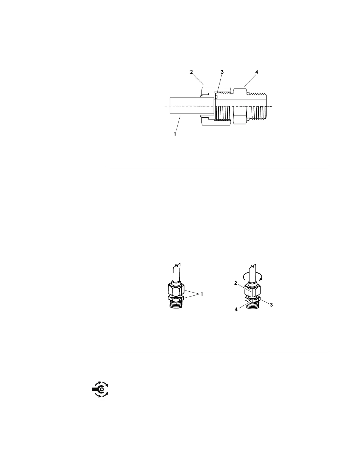
Figure37
1.Tubeorhose
2.Swivelnut3.O-ring
4.Fittingbody
3.Alignthehose/tubeagainstthebodyofthettingsothattheatfaceofthe
hose/tubesleevefullytouchestheO-ringinthetting(Figure37).
4.Useyourhandtothreadtheswivelnutontothetting.Whileyouholdthe
hose/tubeinalignmentwithawrench,useatorquewrenchtotightenthe
swivelnuttotherecommendedtorquevaluewithinthespeciedrangeof
torquevalues;refertotheHose/TubeInstallationTorqueT able(page5–10).
Thisproceduretotightentheswivelnutrequiresadrive-adapterwrench
(e.g.,crowfootwrench).
Note:Itmaybenecessarytouseadrive-adapterwrench(e.g.,crowfoot
wrench)toinstallahydraulictting;refertoCalculatingtheT orqueValues
WhenUsingaDrive-AdapterWrench(page2–7).
g221222
Figure38
1.Marknutandttingbody
3.Initialposition
2.Finalposition4.Extendline
5.Ifatorquewrenchisnotavailableorifspaceattheswivelnutpreventsthe
useofatorquewrench,usethealternativeprocedureFlatsFromWrench
Resistance(FFWR)givenbelow(Figure38).
A.Useawrenchtotightentheswivelnutontothettinguntilyoufeellight
resistancewiththewrench—approximately3.39N∙m(30in-lb).
B.Putamarkontheswivelnutandbodyofthetting.Holdthehose/tubein
alignmentwithawrenchtopreventthehose/tubefromturning.
Groundsmaster
®
3280-D/3320
Page5–9
HydraulicSystem:GeneralInformation
05138SLRevB
 Loading...


