RearFrameandAxleAssembly
g223992
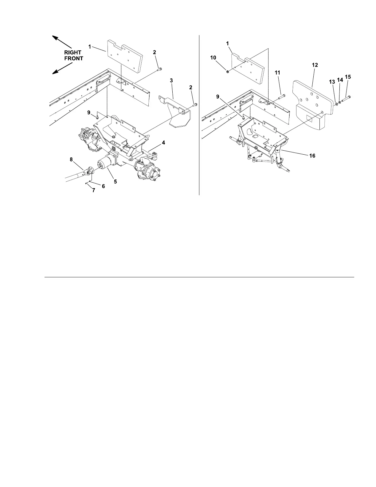
Figure180
1.Rearweight
7.Socket-headscrew(6each)13.Flatwasher(4each)
2.Flange-headscrew(4each)
8.Driveshaft14.Lockwasher(4each)
3.Rearbumper
9.Flange-headscrew(4each)15.Bolt(4each)
4.Rearframeandaxleassembly
(4-wheeldrive)
10.Locknut(2each)16.Rearframeandaxleassembly
(2-wheeldrive)
5.Bi-directionalclutch
11.Bolt(2each)
6.Lockwasher(6each)
12.Rearweight
RemovingtheRearFrameandAxleAssembly
1.Parkthemachineonalevelsurface,lowerthecuttingdeck(orimplement),
shutofftheengine,settheparkingbrake,andremovethekeyfromthe
keyswitch.
2.Blockthefrontwheelswithchockstopreventthemachinefrommoving.
Note:Forassemblypurposes,tagthehydraulichosestoshowtheircorrect
positiononthesteeringcylinder.
3.Disconnectthehydraulichosesfromthesteeringcylinder.Installcleancaps
orplugsonthehydraulichosesandttingstopreventsystemcontamination.
4.On4-wheeldrivemachines,removethe6socket-headscrews(item7in
Figure180)and6lockwashersthatsecurethedriveshafttothebi-directional
clutch.Positionthedriveshaftawayfromthebi-directionalclutch.
5.Ifthemachinehastherearweight(s)attachedtotheframe,removethe
weight(s).
6.Removethefastenersthatsecuretherearofaxleframetothemachine
frameasshowninFigure180.
7.Raisetherearofthemachinesothatbothwheelsareofftheground.Support
therearofthemachineframewithjackstandsorappropriateblocking.
Groundsmaster
®
3280-D/3320
Page7–9
Chassis:ServiceandRepairs
05138SLRevB
 Loading...


