The enclosure has 2 flanges on the bottom. Vaisala recommends that you lead AC (mains)
current through from the left-side flange and the sensor cables from the right.
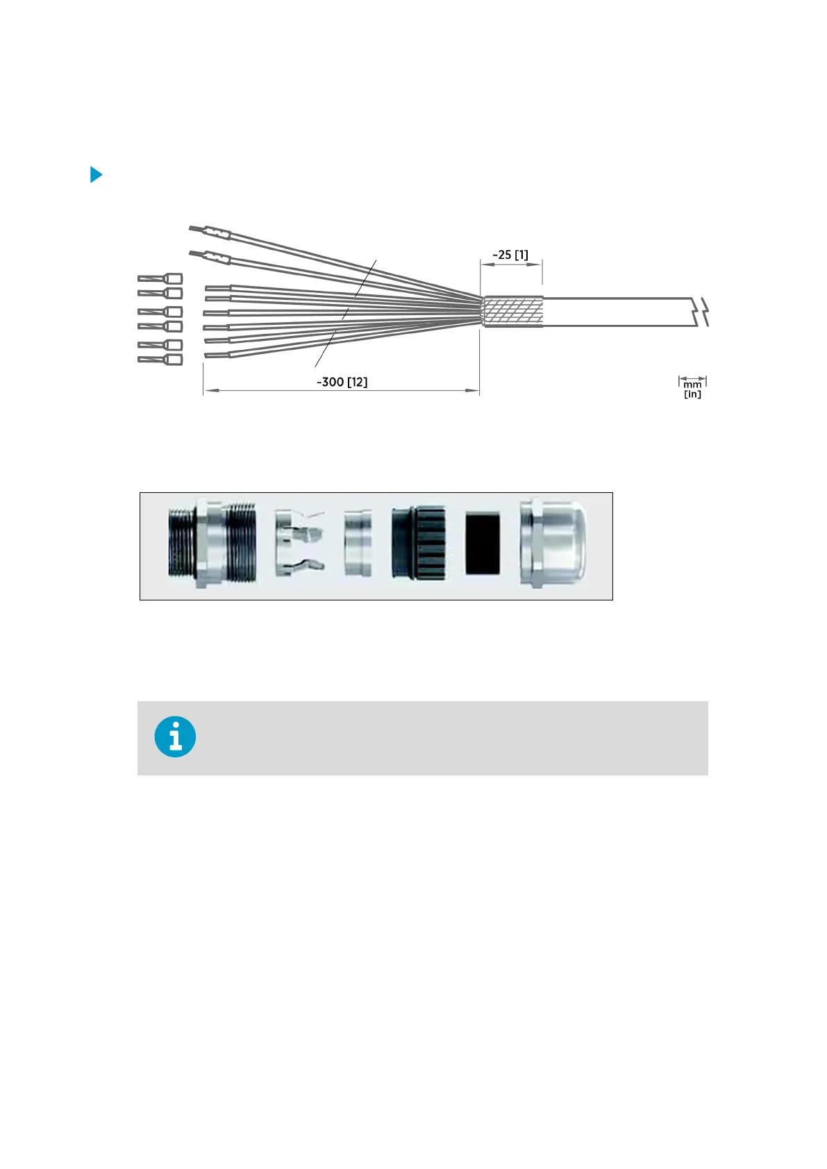
1. Lead the cables to the enclosure through the cabling box.
2. Strip the cables and fold the cable shields over the cable jackets.
3. Lead the cables through the cable glands.
4. Tighten the cable glands around the cable shields.
5. RJ45 connectors do not fit through the cable glands. Cut o the existing connector,
lead the Ethernet cable through a cable gland, and attach a new cable connector to the
cable. For instructions, see the connector documentation.
The Ethernet cable shield is mounted to the connector only. Use rubber sealing
inserts to make sure that the connection is watertight.
6. Inside the enclosure, connect the sensor wires according to the wiring diagram.
7. Isolate all unused wires with a shrinkable tube or electric tape.
More Information
‣
Connecting Sensor and Device Cables (page 218)
17.5.5
Connecting Communication Cables
Connect the data cables according to the wiring diagram.
If your system includes Ethernet communications, connect the Ethernet cable to the
RJ45 connector on the QML data logger.
AWS310/AWS310-SITE Installation Manual M211584EN-F
224