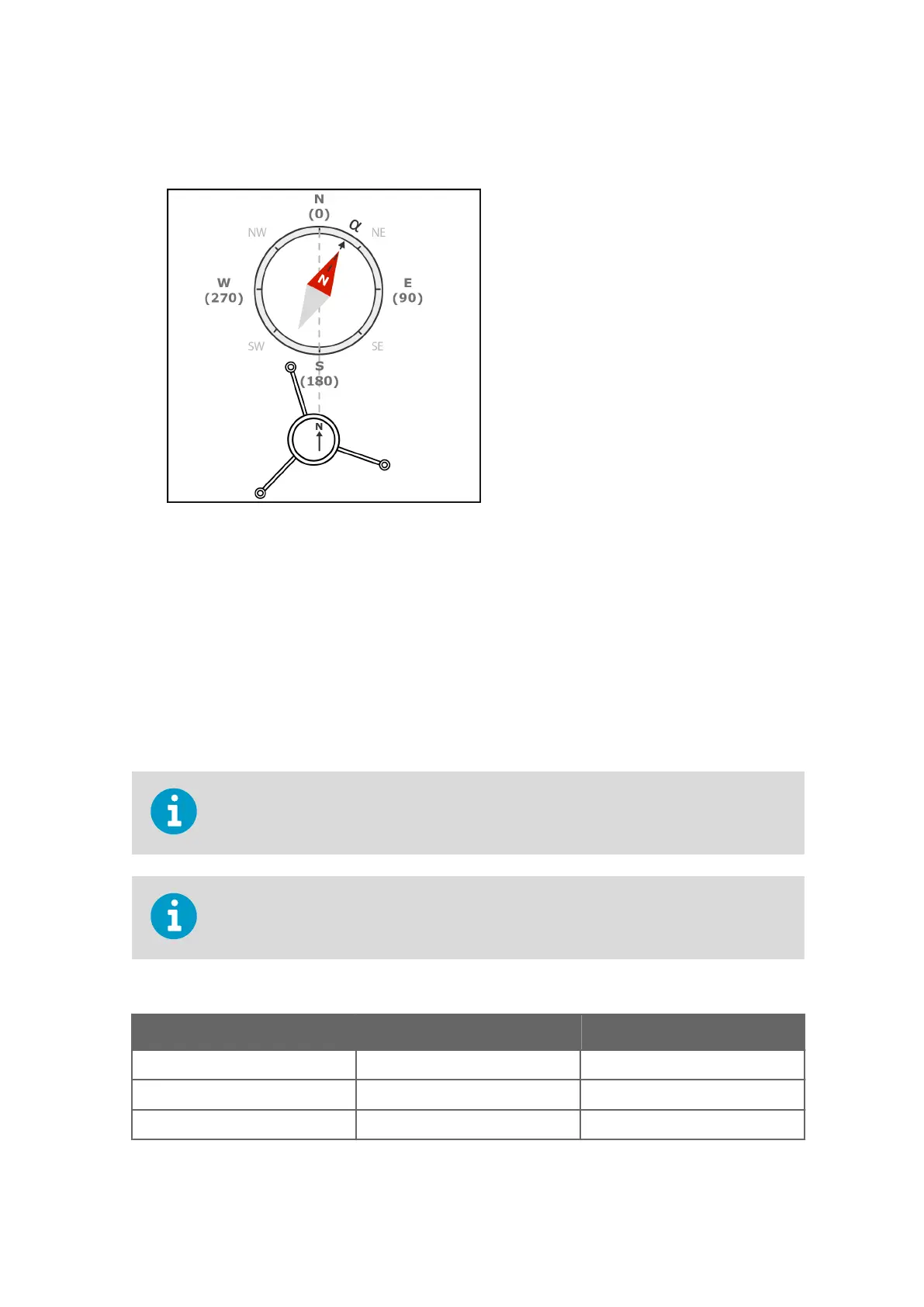
2. To align the sensor, use a compass or other similar method to rotate the sensor so that
the North arrow points North.
3. Tighten the bolts of the mounting kit. Tightening torque 5 Nm.
4. If you cannot align WMT700, measure the deviation angle from North and configure the
wind direction
oset error.
6.3.7
WMT700 Cable Wiring
Connect the WMT700 cable wires as shown in the following table, which lists the pin-outs
for cable 228260 (10 m / 32 ft 10 in). This cable is designed for the standard connection:
operating power, heater power, and RS‑485. The RS‑485 loopback connections in the table
are pre‑connected inside the cable.
The wire colors in the table are not applicable to other cables.
If there are unused wires, make sure they are unconnected and protected. Do not cut o
any wires.
Table 6 Pin-Out for Cable 228260
Description Wire Colors Pin
Operating power supply White 1
Operating power supply ground Gray/Pink 11
Heater power supply Gray, Green, Pink 5 and 6
Chapter 6 – Wind Sensor or Weather Transmitter Installation
63