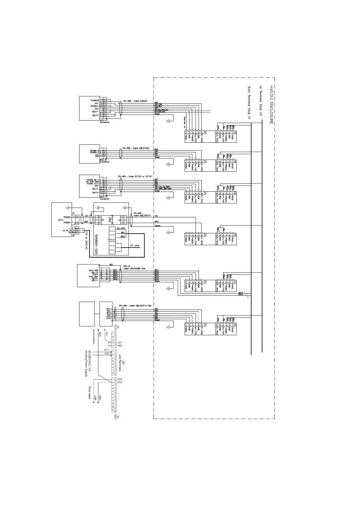
A.4.4 AWS310-SITE RS Line Sensors
(to drawing 1)
(to drawing 2)
= Connection when extra heated VMT703
sensor is used
from terminal strip X1 (drawing 1)
HEAT+ to X1-26A
HEAT- to X1-5A
(Supply from optional DC-Power unit 2 )
QSP431
SURGE
PROTECTOR
Weigh.Rain
MOD1_3
5
SDI-12
OTT Pluvio2L
or Pluvio2
Precipitation Sensor
*
*
(See drawing 1)
< Pluvio2 connector
< Pluvio2L connector
numbering
PWD22
Present
Weather
QSP431
SURGE
PROTECTOR
Present Weather
MOD1_1
3
RS-485
HMP155
Air Temperature
-Humidity
QSP431
SURGE
PROTECTOR
Temp./Hum
MOD1_1
2
RS-485
WMT703,
Wind
Sensors
*
QSP431
SURGE
PROTECTOR
WIND1
COM1
1
RS-485
*
QSP431
SURGE
PROTECTOR
Cloud Height
MOD1_1
4
RS-485
PEN
L1
LNPE
711
IN
OUT
8
12
SURGE
PROTECTOR
CL31
Cloud
Height
Shield wires connected to
Enclosure flange metal strip
WAC155 Heating connection for 20/24VDC
WA15
Wind Sensors
WAC155
RS485 Transmitter
QSP431
SURGE
PROTECTOR
WIND2
COM1
9
RS-485
Figure 89 AWS310-SITE, RS Line Sensors
Appendix A – Wiring Diagrams
255