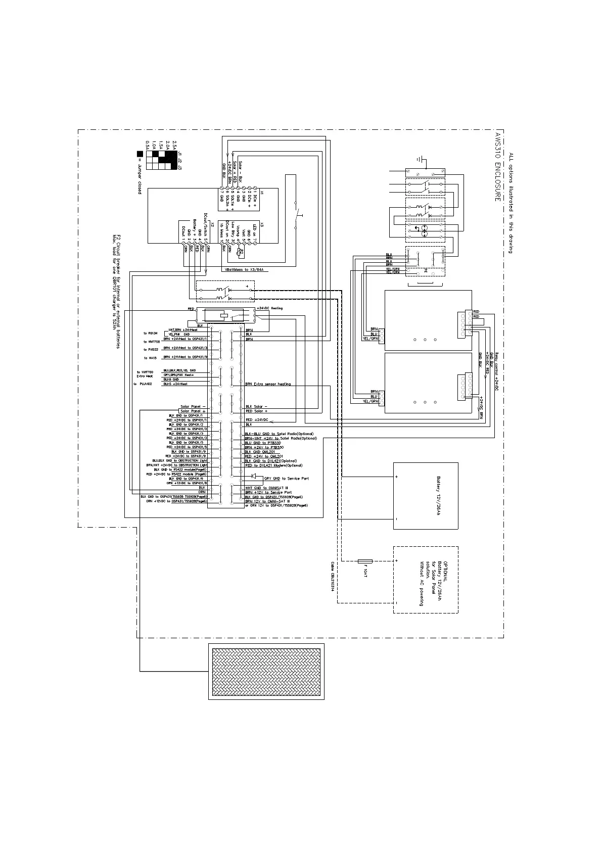
A.4.1 AWS310-SITE Power Connections
QBR101 Battery
Charger
Battery 12V = J4 open
Battery 24V = J4 closed
K1
Sensor Heating 1
Control Relay
3 4 2
1-
5+
K1
Current Limit
Table
B
B
A
A
X1
Power Terminal strip
1 - 20 GND
21 - 24 Sensor heating 1
25 - 27 Extra sensor heating 2 from AC/DC power 2
28 - 30 Solar Panels or external 24VDC connection
31 - 37 Mains power +24V and 12V battery backup
38 - 40 14V from QBR101and 12V battery backup
1
21
2
22
3
23
4
24
5
25
6
26
7
27
8
28
9
29
10
30
11
31
12
32
13
33
14
34
15
35
16
36
17
37
18
38
19
39
20
1
2
3
4
5
6 7 8
9 10
11
12
13
14
15
16
17
18 19
20
40
L N PE
Input AC 100 - 240V
Output DC 24V
13 14
- - -
OK I<
+ + +
L N PE
Input AC 100 - 240V
Output DC 24V
13 14
- - -
OK I<
+ + +
OPTIONAL
POWER UNIT 2
for extra sensor heating
SOLAR PANELS
(to Page 4)
*
= Connections when extra sensor heating is needed
(optional power unit 2 is used)
*
*
X2
AC Terminal strip
MCB
B10A
F2
POWER UNIT 1
AC IN
100 - 240VAC
6 7 8
3 4
5
1
2
V1
2 4 6
1 3 5
BRN
6 7 85
3 4
1 2
MCB
B10A
F1
S1
BLU
PE L N
BLUBRN
YEL/GRN
BRN
BLU
B
A
A
B
331
2 4 42
1
Default Factory setting = 2.5A , 12V
/ Bat.backup Switch
14VDC ON/OFF
1 1a
#