To avoid problems in communication when an RS‑485 connection is used, check that the
ground potential in the station and the receiving end are not too far apart. Make sure that
there is a signal ground connection from the QSP431 connector X1/5 to the signal ground
of the receiving device.
More Information
‣
Installing UHF Antenna (page 79)
‣
Installing 2G/3G Antenna (page 82)
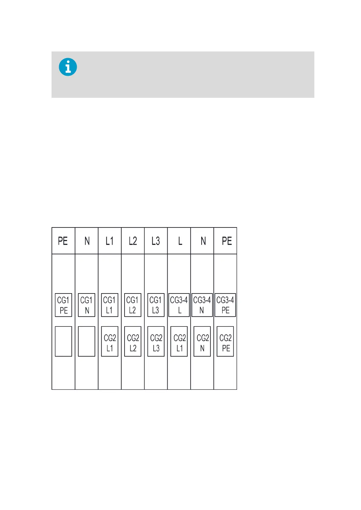
17.6 TERMBOX Connections
The mains cable is lead into TERMBOX through cable gland 1 (CG1). The connection points
are the
five leftmost in the terminal connector block: PE, N, L1, L2, and L3.
• N and L1 are internally wired to the surge arresters.
• Phases L2 and L3 are not pre-wired.
• L2 and L3 connectors are connection points for unusable wires.
Figure 72 Front View of AC Power Connections
More Information
‣
Grounding TERMBOX Signal Cable (page 174)
Chapter 17 – Electrical Installation
225