Installing the machine
13
Original instructions: N4 Impression
Document version: H – 05/2019
4.4 Installing the pneumatics
Risk of injuries through leaking compressed air
and lashing pneumatic hoses
Open or loose pneumatic connections can cause severe in-
juries.
h Make sure that during installation of the pneumatic
hoses and of the service unit compressed air is is not run
-
ning through the hoses and connections.
h After installing the pneumatic hoses but before running
compressed air through the hoses and connectors, check
if the hoses are securely inserted into the correct connec
-
tors and are not damaged.
h Do not run compressed air through damaged hoses and
connectors.
The spindle may suffer bearing damage and
electrical damage if the compressed air is
contaminated
The incoming compressed air must be dry and oil-free ac-
cording to ISO
8573-1 because the service unit only serves as
an indicator for contaminated air.
Air purity according to ISO 8573-1
Solid particles Class 3 Filtration degree
better than 5 µm
for solid particles
Water content Class 4 Maximum pressure
dew point +3 °C
Residual oil content Class 3 Maximum oil con-
tent: 1 mg/m³
h Make sure that the compressed air meets the mentioned
requirements.
h Only connect the machine to the compressed air supply
via the provided service unit.
The spindle requires compressed air for the following tasks:
For the opening and closing of the collet chuck during
tool change.
For the sealing air which prevents foreign bodies from
entering the spindle.
Air consumption of the machine:
approx. 35 l/min at 4 bar (1.2 cfm at 60 psi)
approx. 50 l/min at 8 bar (1.8 cfm at 120 psi)
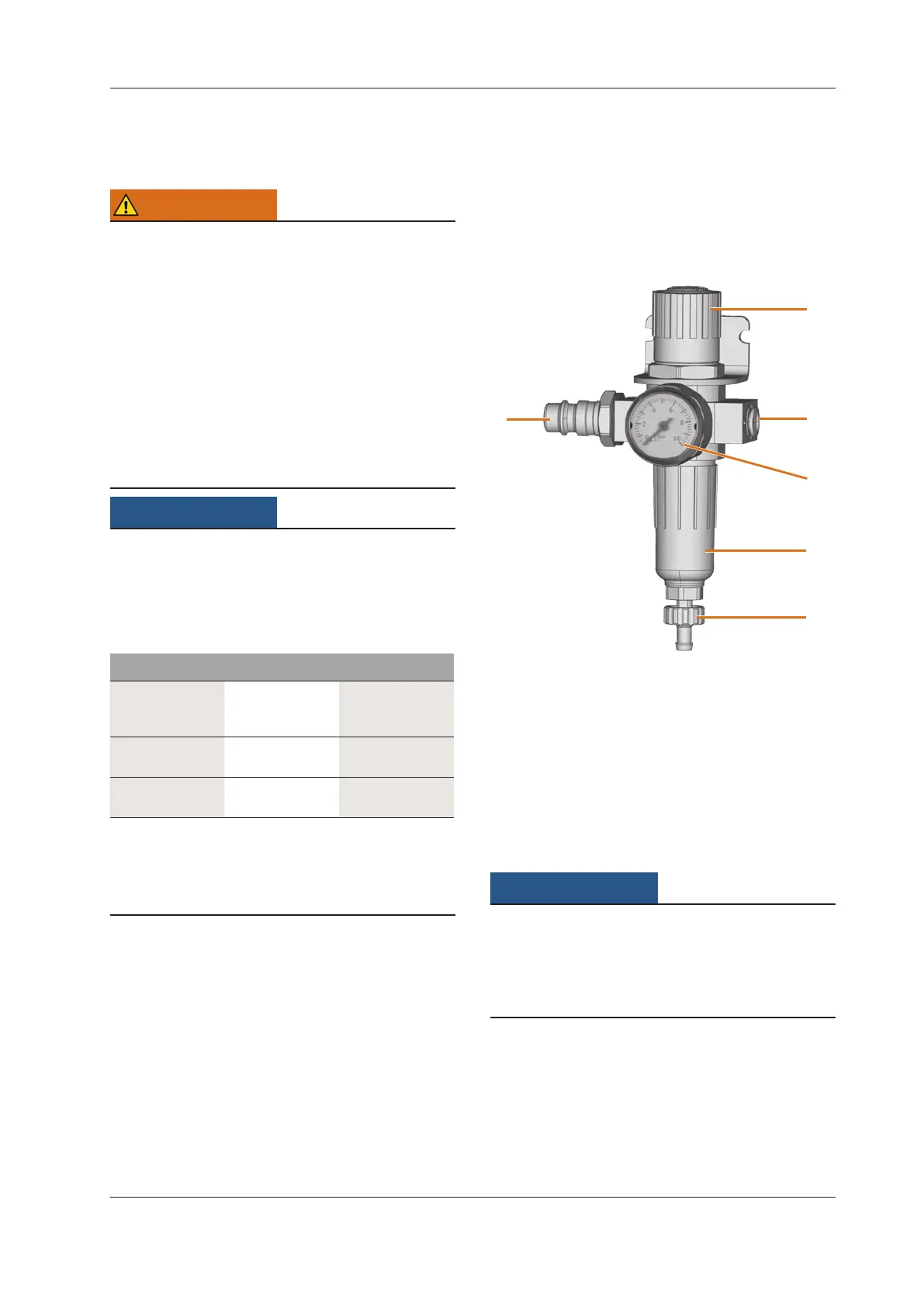
4.4.1 Overview service unit
Via the service unit you connect the machine to your com-
pressed air supply and regulate the incoming pressure for the
machine.
Fig. 5:
1
2
3
4
5
6
The service unit: regulating and checking the air pressure
[1] Rotary knob for pressure regulation
[2] Pneumatic connection to the machine (ø 6 mm)
[3] Manometer for monitoring the outgoing pressure
[4] Water separator
[5] Discharging screw
[6] Standard pneumatic connection
4.4.2 Mounting the service unit on the machine
Failure of the water separator caused by a
wrong alignment of the service unit
The service unit must always be mounted in an upright po-
sition because otherwise the water separator will not work.
h Mount the service unit in an upright position (
Fig. 5).
On the left side of the machine are two drillings which you
can use to mount the service unit on the machine.
M1. Remove the two blind screws in the drillings.
M2. Mount the service units with the provided lens head
screws in an upright position.