Running the machine
20
Original instructions: N4 Impression
Document version: H – 05/2019
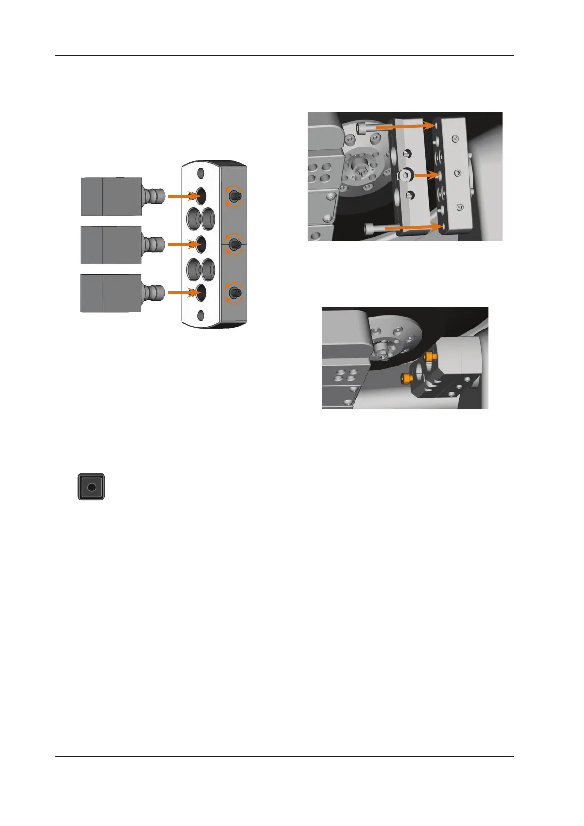
M4. Immobilize the blocks with the screws which you loos-
ened in step M2. Use the provided torque wrench (1.8
Nm) for
this and tighten the screws until the torque
wrench triggers.
Fig. 18:
2.
1.
3.
Inserting the blocks
5.5 Using an optional abutment holder
With the optional abutment holders your machine can pro-
cess abutments with prefabricated connection geometries.
b
Prefabricated abutments usually require manufacturer
specicabutmentholders.Dierentabutmentholder
models can be obtained from customer service.
5.5.1 Installing the PreFace® abutment holder
S1. Move the spindle back to the default position
by clicking on the depicted icon.
M2. Open the working chamber door of the machine and
remove all items from the blank holder.
M3. Switchothemachine.
You can manually rotate the blank holder.
M4. Rotate the blank holder into a vertical position (
Fig.
19).
M5. Place the abutment holder onto the blank holder and
screw the long screws of the abutment holder into the
blank holder manually.
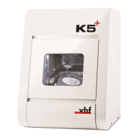
Fig. 19: Screwing in the abutment holder
M6. Turn the blank holder clockwise up to the stop.
M7. Screw down the 2 screws with the provided ratchet.
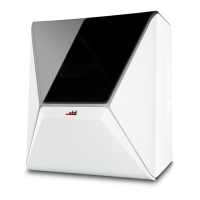
Fig. 20: Immobilizing the abutment holder
M8. Close the working chamber door of the machine.
M9. Switch on the machine.
5.5.2 Demounting the PreFace® abutment holder
M1. Remove inserted prefabricated abutments from the
abutment holder (if any).
M2. Loosen the screws of the abutment holder (
Fig. 20)
and remove it.
5.6 Mounting and removing PreFace® abutments
M1. Loosen the screw at the PreFace® abutment holder with
a hexagonal socket screwdriver. You do not need to re-
move the screw completely.
M2.
Carefully push the loosened screw of the PreFace® abut-
ment holder downwards into the holder.