Installing the machine
14
Original instructions: N4 Impression
Document version: H – 05/2019
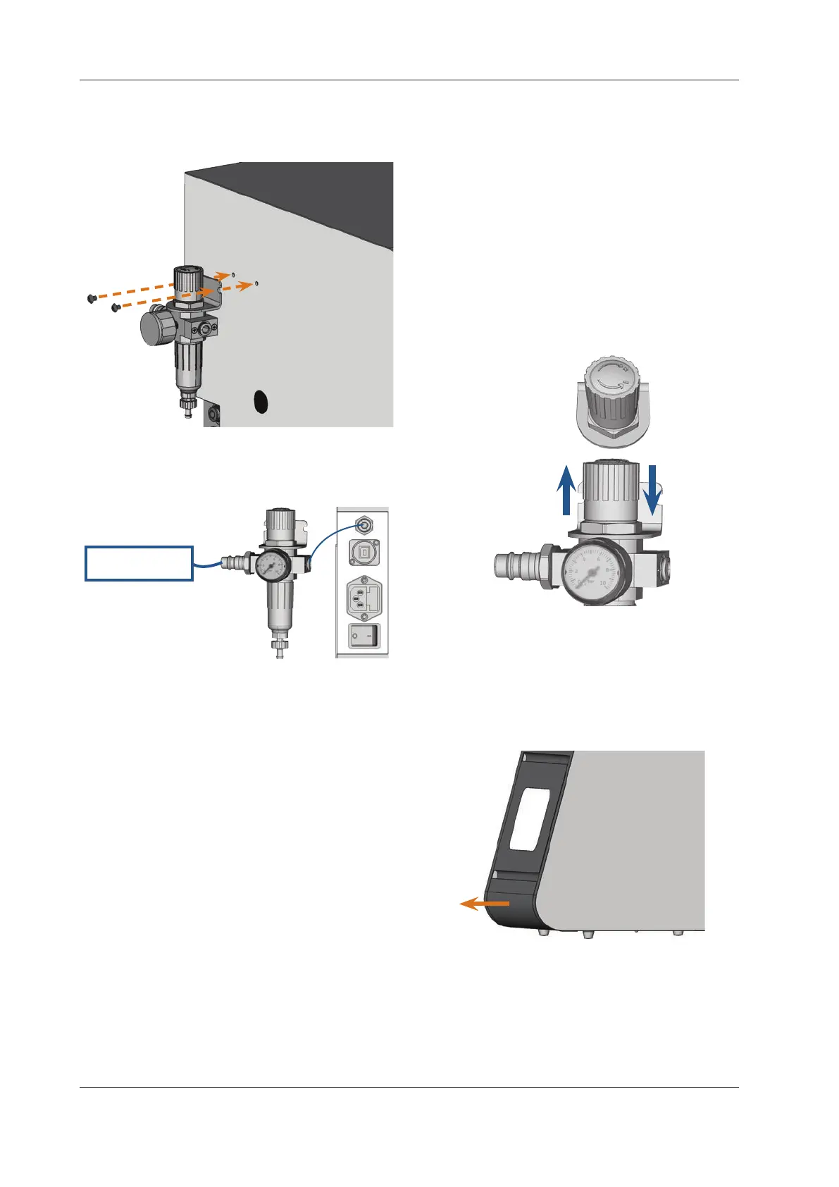
Fig. 6:
Mounting the service unit on the machine
4.4.3 Installing the pneumatic hoses to the service unit
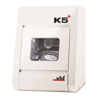
Fig. 7:
External compressed
air supply
Installation of the service unit (schema)
M1. Shutotheexternalcompressedairsupply.
M2. Via the provided pneumatic hose connect the right
pneumatic connection of the service unit [2] with the
pneumatic connection of the machine.
M3. Connect the external compressed air supply with the
standard pneumatic connection of the service unit [6].
M4. Check the installation carefully for errors and damage.
Do not conduct compressed air through damaged or
loosehosesandconnections!
M5. Open the external compressed air supply.
M6. Check the air pressure on the manometer [3]. If it does
not lie between 4 bar and 8 bar, adjust it with the ser
-
vice unit (
chapter 4.4.4).
4.4.4 Setting the air pressure with the service unit
Setting the air pressure is only necessary if the air pressure
shown by the manometer does not lie between 4 bar (60 psi)
and 8 bar (120 psi).
The service unit is connected to your compressed air
supply.
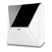
M1. Pull the rotary knob on top of the service unit a little
bit upwards.
M2. Turn the rotary knob in the desired direction until the
pressure lies between 4 bar and 8 bar – 4.5 bar (65 psi)
are recommended:
Turning it towards „+“ you increase the pressure
Turning it towards „–“ you decrease it
M3. Push the rotary knob down again.
The knob is locked and cannot be changed inadver
-
tently.
Fig. 8:
1.
3.
2.
Setting the air pressure
4.5 Filling the cooling liquid tank
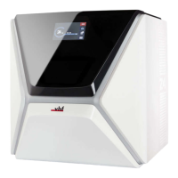
M1. If the working chamber door is open, close it.
M2. Pull the cooling liquid tank out of the machine as far
as it goes.
Fig. 9: Pulling out the cooling liquid tank
M3. Fill the cooling liquid tank with 4 litres of tap water.
M4. Add 0.2 litres of cooling lubricant.
You have a 4.2 litre emulsion of water and cooling lu
-
bricant with a mixing ratio of approx. 5
%.