Installing the machine
15
Original instructions: N4 Impression
Document version: H – 05/2019
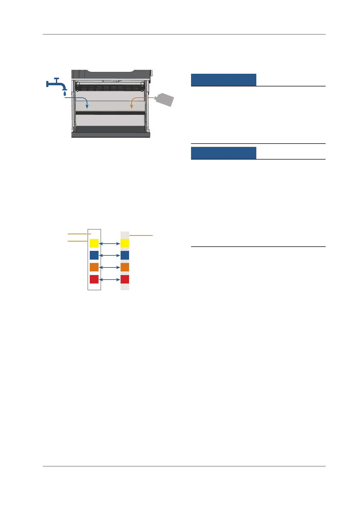
Fig. 10:
1.
2.
Mixing water and cooling lubricant
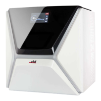
M5. Take a pH testing strip from the provided tank and im-
merse it into the cooling liquid for a few seconds.
n
Close the tank with the pH testing strips completely
after usage. Otherwise the testing strips will become
useless when exposed to air humidity for too long.
M6. Compare the four coloured squares on the testing strip
withthescaleonthecontainer.Youcanndthedeter
-
mined pH value in the column of the scale where the
colours match t
he colours on the testing strip.
Fig. 11:
9
1
2
3
Comparison of pH Scale with testing strip
For technical reasons colours may deviate
[1] Determined pH value (exemplary value)
[2] Scale on container
[3] Testing strip
M7. If the pH value lies beneath 9, add 50 millilitres cooling
lubricant to the emulsion. Repeat steps M5 to M7, but
no more than twice. After that dispose of the cooling
liquid completely (
chapter 6.9, page 29) and
start again with step M3.
M8. If the pH value of the cooling liquid is correct, close the
cooling liquid tank.
4.6 Establishing the electric connection
Damaging of the machine through heavy
voltage fluctuations
Heavyvoltageuctuationscandisruptthecontrolunitand
can cause a failure of the system.
h Plug the machine’s power cord in a dedicated circuit cur
-
rent or ensure that no devices are connected that can
cause
heavyvoltageuctuationwhenswitchedon.
Damaging of the machine if the transport lock
and the CAM computer are installed
When you connect the machine to the electrical source and
the CAM computer is connected, the machine starts referenc-
ing. During this process, the transport lock which is installed
at delivery can damag
e the mechanics of the machine.
h Do not connect the machine to the electrical source if
the CAM computer and the transport lock are installed.
h If the transport lock is installed, disconnect the USB
connector between the machine and the CAM computer
before connecting the machine to the electrical source.
M1. Plug the provided power cord into the power connec
-
tion at the connection panel of the machine.
M2.
Put the plug of the cord into a socket that is protected
by a Residual Current Device / Ground Fault Circuit In
-
terrupter.
4.7 Removing the transport lock
Beforeoperating the machine for the rst time, youmust
remove the transport lock. The transport lock prevents the
spindle from getting damaged during transport.
M1. Disconnect the USB connector between the machine
and the CAM computer.
M2. Connect the machine to the electrical source.
M3. Switch on the machine.
M4. Open the working chamber door.
M5. Carefully pull the transport lock upwards and then out
of the working chamber.
M6. Clean the working chamber from parts of the transport
lockthatmayhavebrokeno.