Machine maintenance and cleaning
31
Original instructions: N4 Impression
Document version: H – 05/2019
6.12 Checking the service unit
Damaging of the machine when compressed air
is contaminated
Compressedairthatdoesnotfulltheguidelinesforpurity
according to ISO 8573-1 can damage the machine (
page
13).
h Check the water separator of the service unit daily for
contamination.
h Never use the machine if there is water, oil or solid parti
-
cles in the water separator.
6.12.1 Checking the water separator for condensate
Condensate in the separator usually points to compressed air
not being dry enough.
M1. Check if water, oil or solid particles piled up in the wa
-
ter separator.
Inthis caseswitchthe machineoimmediatelyand
proceed as follows:
M2. Check the compressed air supply and make sure that the
compressedairfullstherequirementsforairpurityac
-
cording to ISO 8573-1 (
chapter 4.4.1, page 13).
Donotusethemachineuntilthecompressedairfulls
thisrequirement!
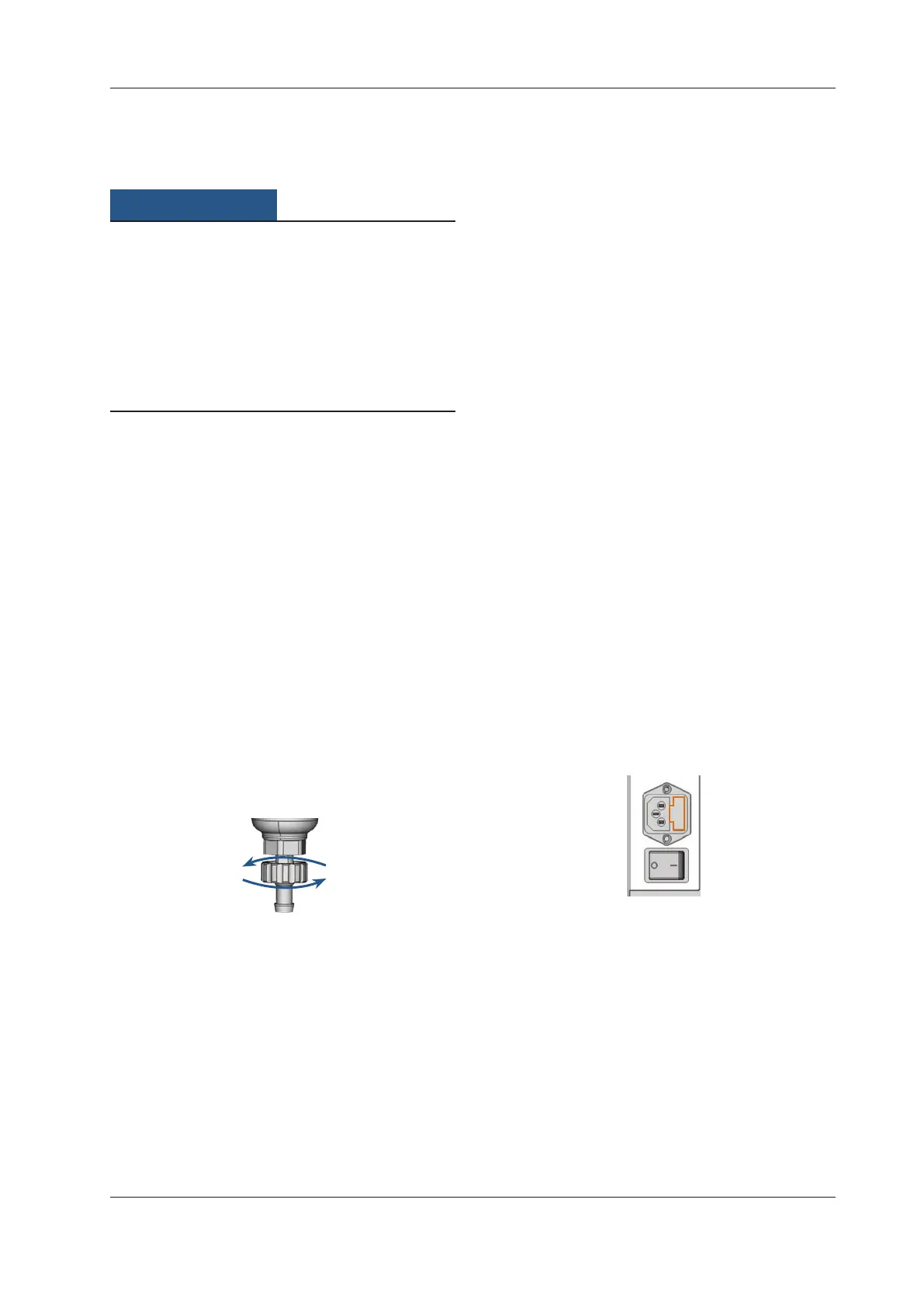
M3. Drain the water separator by turning the discharging
screw counter-clockwise.
The condensate is blown out downwards under pres
-
sure.
M4.
Close the discharging screw again by turning it clock-
wise.
Fig. 37: Opening / closing the discharging screw at the service unit
6.12.2 Exchanging / cleaning the contaminated lter
cartridge
Youhavetocleanorexchangetheltercartridgeinthewater
separator in case of strong contamination.
n
A strongly contaminated cartridge can lead to a pres-
sure loss.
If
thecompressedairfullsthe requirementsforairpurity
accordingtoISO8573-1,theltercartridgeusuallydoesnot
have to be changed.
h Iftheltercartridgeiscontaminated,checkthepurityof
your compressed air (
page 13).
You exchange or clean the lter cartridge as
follows:
M1. Disconnect the machine from the compressed air sup-
ply.
M2.
Unscrew the bowl of the water separator.
M3. Untightenthelterscrewbelowtheltercartridge.
M4. Pullouttheltercartridgeandcleanitifnecessary.
b
Anewltercartridgeisavailableassparepartfromcus-
tomer service.
M5.
Inserttheneworcleanedltercartridgeandreassem-
ble the water separator.
6.13 Exchanging the main fuse
n
Use only a fuse of the type T6,3A L250V as replacement
fuse.
The internal power supply of the N4 Impression has a main
fuse that is accessible from outside and can be replaced if
necessary.
b
A new main fuse is available as spare part from custom-
er service.
M1.
Turnothemachineatthemainpowerswitchanddis-
connect the machine from any electrical source and the
com
pressed air suppl
y.
M2. Remove the power cord from the connection panel.
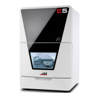
M3. Remove the cover of the fuse.
Fig. 38: Cover of the fuse (marked orange)
M4. Remove the defective fuse and replace it with a new
fuse of the type T6,3A L250V.
If you do not have a replacement fuse ready, take the
replacement fuse from the right side of the fuse cover
and put it into the left side of the fuse cover.
M5. Remount the fuse cover.