187
FNC
57
1
2
M
3
○○○○
D P L S Y
S1
S2
D
X Y M S
D.b R.b
KnX KnY
KnM KnS
T C
D,R
V,Z
UnG
K,H
E
" $"
S1
D
S2
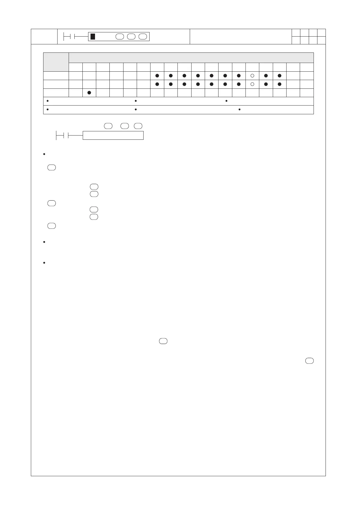
S1 : the frequency of pulses to be output
S2 : the number of pulses to be output
D : the pulse output point
PLSY K500 D100 Y0
X20
D
S1
S2
S1
S2
D
S2
S2
S1
S1
S2
S2
Operand
Devices
Pulse Y Output
VS1 / VS2 series S1 = 1~50,000 VS2 / VS3 series S1 = 1~200,000 VSM-28ML S1 = 1~1,000,000
16-bit instruction S2 = 1~32,767 32-bit instruction S2 = 1~2,147,483,647
D = Y0~Y3
When X20=“ON”, the Y0 uses 500 Hz frequency rate (i.e. 500 pulses per second) to produce the specied quantity
of pulses that number is assigned by the content value of D100.
designates the output pulse frequency the available range of the PLC:
The VS1 or VS2 series is from 1 to 50,000Hz; VSM or VS3 series is from 1 to 200,000Hz; VSM-28ML is from 1
to 1,000,000Hz.
If the value of is less than 1, regards it as 1.
If the value of is exceeding the upper limit of the range, regards it as the maximum value.
If the value of is equal to 0, the quantity of pulses is unlimited for continuous outputs.
If the value of is less than 0, the PLC will regard that as an operating error and the M9067 will be “ON”.
When the conditional contact X20 becomes “OFF” during the pulse output, pulse outputs will be stopped and the
pulse output point will also turns “OFF”; When the X20 becomes “ON” again, it will restore to generate pulses from
the rst one.
Since the pulse output function at the Y0~Y3 are the same, below we use the Y0 as an example to describe the
related special devices.
The M9340 displays the status of the Y0 axis.
Any instruction which is related to the axis Y0 and is executed successfully, will continuously occupy the axis Y0,
until the condition contact becomes “OFF”.
Therefore, before to activate this instruction, should pay attention to the status of the M9340.
If the M9340 is already “ON”, it indicates that axis Y0 is occupied by other relevant instruction to generate pulse or
positioning. So, this instruction will not be executed even though the condition contact is “ON”.
When the M9340 is “OFF”, it indicates that axis Y0 is READY to accept and execute this instruction.
The M9341 is a pulse output monitor ag of the axis Y0.
When the axis Y0 is outputting pulse, the M9341 turns “ON”.
The M9342 is a positioning completed ag of the axis Y0.
When the number of pulse outputs assigned by is arrived, the M9342 turns “ON”.
When the condition contact is “OFF”, the M9342 will also turn “OFF”.
The M9343 is a ag for abnormal stop at the axis Y0.
The stop ag turns “ON” at the moment that the Y0 is generating pulses and the number of pulses assigned by
is not arrived yet, the pulse outputting will be stopped promptly. The M9343 will turn “ON” to indicate the stop is
abnormal.
When the condition contact is “OFF”, the M9343 will also turn “OFF”.
The M9345 or M9346 is the stop signal of the axis Y0.
When either one of the signals is “ON”, the Y0’s pulse outputting at this instruction will be stopped promptly. After
the stop signal is clear, this instruction must be reactivated to enable pulse outputting again.
The (D9351, D9350) display the current speed of axis Y0.
When the instruction is executed, that will display the current pulse frequency of the axis Y0's output.
The (D9353, D9352) display the number of pulses that the axis Y0 has been output.
When the power switches “ON”, the initial value is 0. Afterwards, that will display the accumulated number of the
axis Y0’s output pulses.
designates the number of output pulses, the available range is 0~2,147,483,647.
designates the pulse output point. It can only designate to the point Y0~Y3 to be the pulse output device and
must use a transistor main unit.


 To Next Page