195
D A B S D
S1
S2
D
n
FNC
62
1
2
M
3
○○○○
X Y M S
D.b R.b
KnX KnY
KnM KnS
T C
D,R
V,Z
UnG
K,H
E
" $"
S1
D
S2
n
X20
ABSD D0 C0 M0 K4
S1
S2
D
n
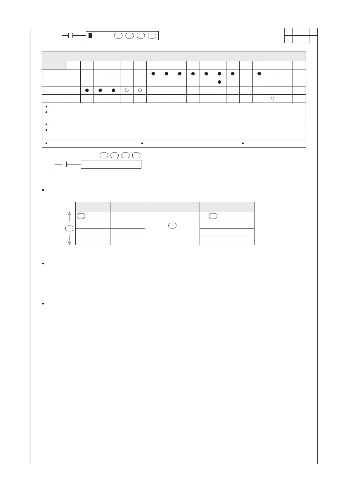
Operand
Devices
Absolute Drum Sequencer
S1 : the head device ID number of the comparison table
S2 : the ID number of the counter for the comparison
D : the number device ID number of the comparison result
n : the number of comparison section groups
The instruction is a Multi-Section Compare instruction and generally is operated for multi-section absolute drum
sequencer.
When X20= “ON”, the current value of the selected counter C0 is compared against a user defined data table
[(D0, D1), (D2, D3), (D4, D5) and (D6, D7), there are 4 groups of upper/lower limit], and the results are stored on
M0 ~ M3 respectively.
At each group, if the condition is met [Lower Limit ≤ Comparison Value ≤ Upper Limit], the corresponding output
point will be turned “ON”; Otherwise, the comparison value is not placed between Upper Limit and Lower Limit, the
corresponding output point will be turned “OFF”.
When X20= “OFF”, the “ON”/ “OFF” statuses at M0~M3 will remain as same as before it is disabled.
n
D
M0=1
M1=0
M2=1
M3=0
S2
C0=100
S1
D0=50
D2=0
D4=80
D6=120
D1=200
D3=50
D5=120
D7=300
Lower Limit
Upper Limit
Comparison Value Comparison Result
The 16-bit instruction, S1 occupies (2×n) components, D occupies n components.
When S1 designates to Kn X, Kn Y, Kn M or Kn S, that Kn must be K4 and the ID number of the X, Y, M or S must be a multiples
of 8
The 32-bit instruction, S1 occupies (4×n) components, D occupies (2×n) components.
When S1 designates to Kn X, Kn Y, Kn M or Kn S, that Kn must be K8 and the ID number of the X, Y, M or S must be a multiples
of 8
The 16-bit instruction, S2=C0~C199 The 32-bit instruction, S2=C200~C255
n=1~64