202
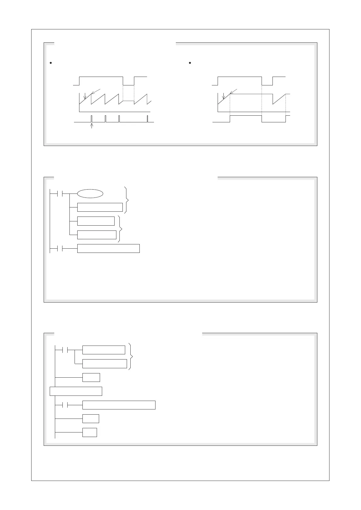
X20
(D0)
(D2)
(D1)
M9029
X20
(D0)
(D2)
(D1)
M9029
MOV K10 D9039
MOV K10 D0
MOV K110 D1
RAMP D0 D1 D2 K500
M9039
M9000
X20
MOV K1000 D11
FEND
MOV K100 D10
ITA10
IRET
END
RAMP D10 D11 D20 K1000
M9000
X20
Set the initial value of the ramp variation at 100 and the destination at 1000.
ITA10 is the interrupt pointer of the time interrupt at 10ms.
Time of the entire process of the RAMP instruction (the current
value of D20 changes from the set value of D10 to the set value
of D11) will be 10ms × 1,000 = 10,000ms = 10 Sec.
When the RAMP instruction is performed, the operation mode will depend on the status of Special Relay M9026.
If M9026 = “OFF”, it will generate contiguous
ramp results. (Repeat Mode)
“ON” for a Scan Time
Settle the Scan Time at 10ms.
Set the initial value of the ramp variation at 10 and the
destination at 110.
Time of the entire process of the RAMP instruction (the current value
of D2 changes from the set value of D0 to the set value of D1) will be
10ms × 500 = 5,000ms = 5 Sec.
Since the PLC's Scan Time is settled at 10ms (each Scan Time is consistent) the ramp variation is like a Linear
Gradient. However, in the program model referred above, it should be noted that the set value of the constant
Scan Time is larger than the maximum value of the actual Scan Time a little. Otherwise, the constant Scan Time
function would be useless. To oversee the D9012 register will get the maximum value of the actual Scan Time.
Operation Modes (Swappable by Flag M9026)
A Program Model that Uses the Constant Scan Time Function
A Program Model that Uses the Time Interrupt Function
If M9026 = “ON” , it will generate only one
ramp results. (Hold Mode)