201
R A M P
S1
S2
D
n
FNC
67
1
2
M
3
○○○○
X Y M S
D.b R.b
KnX KnY
KnM KnS
T C
D,R
V,Z
UnG
K,H
E
" $"
S1
D
S2
n
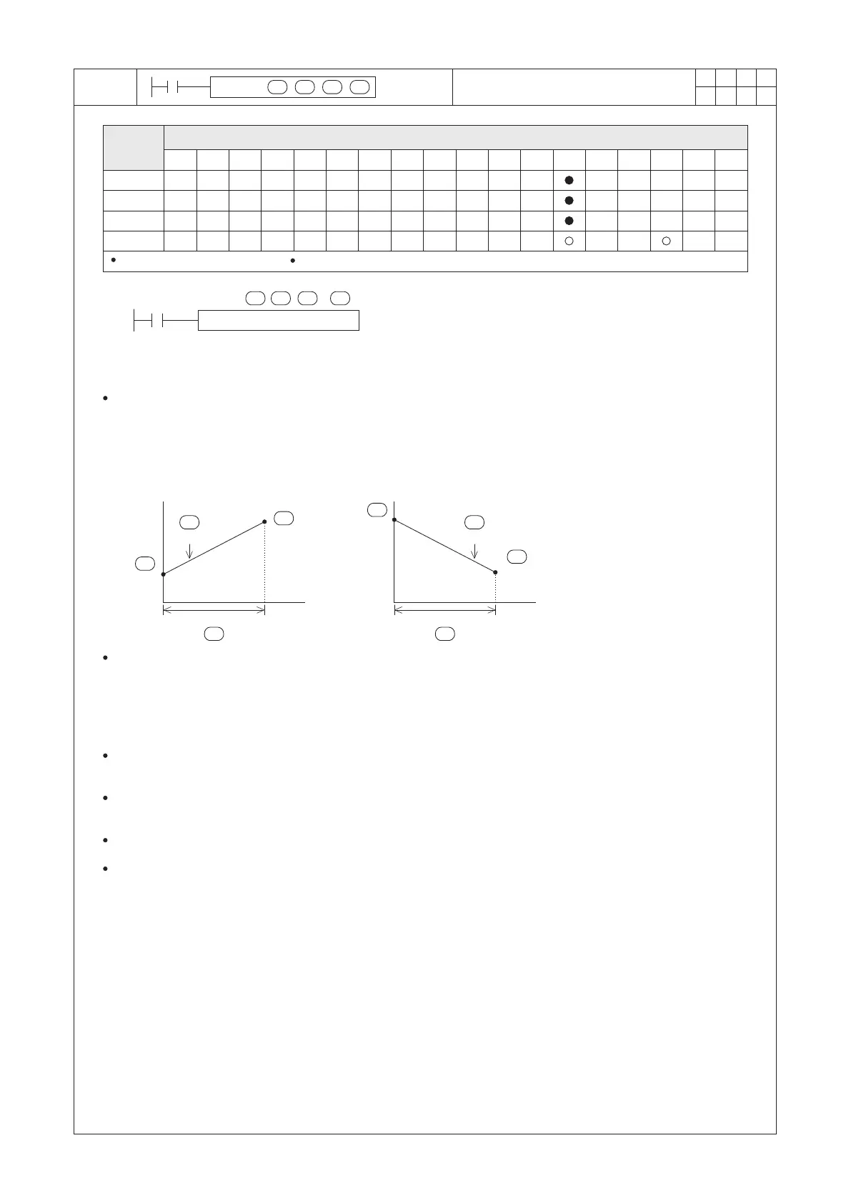
RAMP D0 D1 D2 K500
X20
(D0)<(D1) (D0)>(D1)
(D0)
(D2)
(D1)
(D2)
(D1)
(D0)
D
S1
S2
n
D
S2
S1
D
S2
S1
n n
Operand
Devices
Ramp Variable Value
n = 1~32,767
D occupies 2 components
S1 : the initial value of the ramp variation
S2 : the destination value of the ramp variation
D : the value of the course of the ramp variation
n : to assign the using number of times that ramp
action is completed
Write the initial point value of the ramp variation to D0 and write the destination value of the ramp variation to D1.
When X20=“ON” and (D0)<(D1), then the current value of D2 will increase from the smaller set value of D0 to the
bigger set value of D1.
When X20=“ON” and (D0)>(D1), then the current value of D2 will decrease from the bigger set value of D0 to the
smaller set value of D1.
It takes 500 of PLC’s Scan Times for the current value shifted from the set value of D0 to the set value of D1.
When the instruction is activated,
the “course” value of the ramp
variation will be reflected on (D2)
while the number of the scanned
times will be reflected on (D3).
500 Program Scans500 Program Scans
As shown in the diagram above, whether the continuous curve of D2, appears to be in Linear Gradient is closely
correlated to the Scan Time of PLC. Generally PLC does not always take the same Scan Time.
Thus, if the wanted characteristic of the RAMP instruction's result is a Linear Gradient, the interval of the RAMP
instruction is performed must be equal at each time. In terms of this purpose, it’s suggested to use the constant
Scan Time setting function or the interrupt function. (Please reference to the program examples in next page.)
When X20= “ON” → “OFF”, the instruction will be disabled and D3 will be cleared as “0”; And if X20 is set “ON”
again, the instruction will restart from the beginning.
When the execution of the instruction is completed, M9029= “ON” and the content value of D2 will be restored to
the setting value of D0.
The instruction can work with the analog output to incorporate the action of the buffered start/stop.
If X20= “ON” and PLC turns from STOP to RUN, please clear D3 as “0” at the beginning of the program.