213
P R
S
D
1
2
M
3
○○○
FNC
77
X Y M S
D.b R.b
KnX KnY
KnM KnS
T C
D,R
V,Z
UnG
K,H
E
" $"
S
D
PR D0 Y20
X20
Y27~Y20
〜
〜
〜
〜
〜
〜
〜
〜
T T T
〜
〜
Y27~Y20
〜
〜
〜
〜
〜
〜
〜
〜
〜
〜
T T T
〜
〜
S
D
S
D
○
Operand
Devices
Print ASCII Code
S occupies 4 components
D occupies 10 components
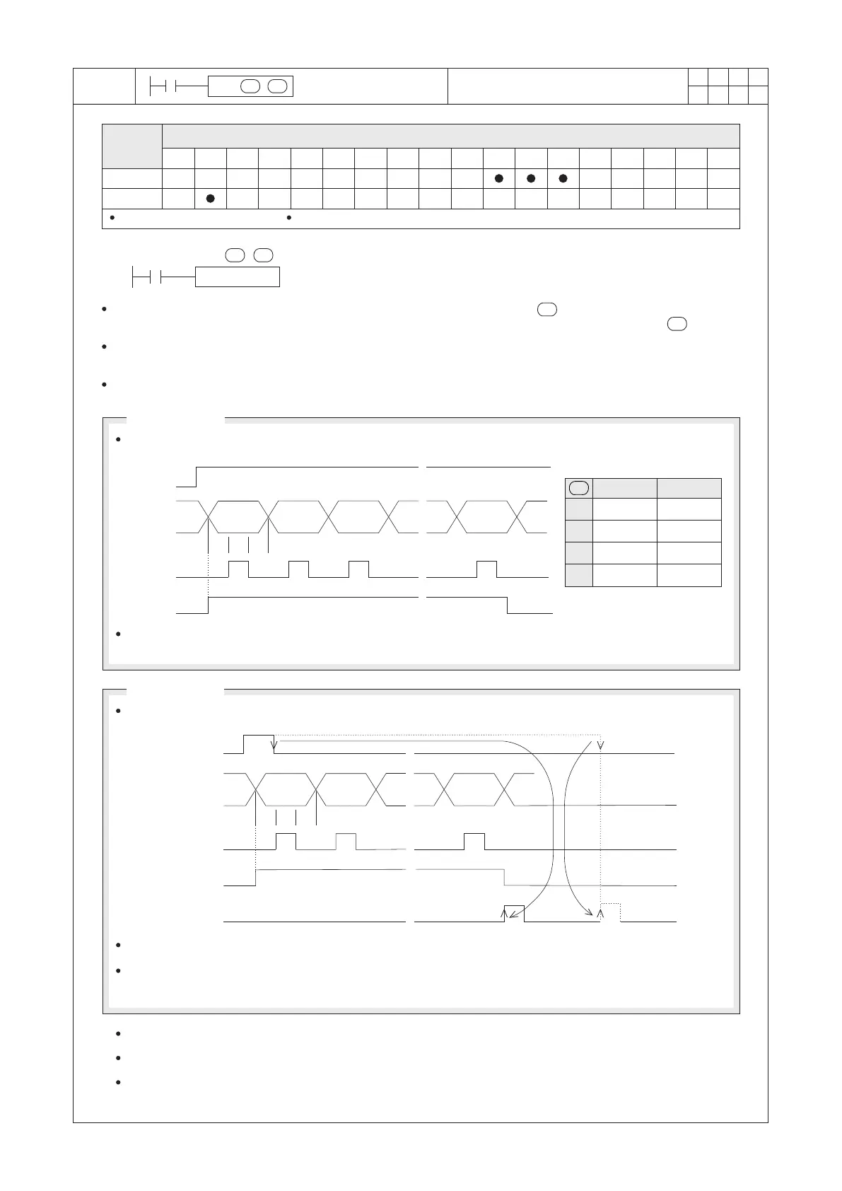
S : the source devices where ASCII codes are stored
D : the output points to export the ASCII codes
The instruction will read ASCII codes of 4 (or 8) source registers (started from and each coed will take a byte).
And then, orderly output the ASCII codes to the designated consecutive 8 output points (started from ).
The process referred above designates 8 points from Y27 (the first bit) to Y20 (the last bit), those are the data
output points. It also designates Y30 as the scan signal and Y31 as the monitoring signal.
There are two operation modes for the PR instruction, depending on the status “ON”/“OFF” of M9027.
st
1 word
nd
2 word
rt
3 word
th
8 word
Up 8 bits
Down 8 bits
D0
D1
D2
D3
S
th
8 word
th
4 word
th
6 word
nd
2 word
th
7 word
rd
3 word
th
5 word
st
1 word
T : The period of one PLC's Scan Time
Activation
signal X20
Scan
signal Y30
Monitoring
signal Y31
If X20 turns “OFF” during the instruction is performed, the instruction is disabled then the data output will be
discontinued. When X20 turns “ON” again, data will be transferred from the first letter.
last word
st
1 word
nd
2 word
T : The period of one PLC's Scan Time
Activation
signal X20
Scan
signal Y30
Monitoring
signal Y31
Execution Completed
Flag M9029
The PR instruction can be used once only in the program.
When performing the instruction, please use the constant Scan Time function to fix the PLC's Scan Time or place
the instruction in a subroutine of the timer interrupt function, they will fix the time value of “T” which shown in the
diagram above.
The activation signal
does not have to be
active all the time.
M9027= “OFF”
To generate the 8 words of sequence outputs. The operation sequence diagram is shown below:
M9027= “ON”
To generate the 16 words of sequence outputs. The operation sequence diagram is shown below:
The code “00H” (NUL) represents the end of the string and the following words will not be processed.
If X20 always stays “ON”, the output will be stopped automatically when all data export is finished.
Meanwhile M9029 will not be activated until X20 turns “OFF”.
Please use a transistor output unit for the output points designated by the instruction.
 Loading...