214
D PF R O M
m1 m 2
D
n
1
2
M
3
○
FNC
78
○○
X Y M S
D.b R.b
KnX KnY
KnM KnS
T C
D,R
V,Z
UnG
K,H
E
" $"
m1
m2
D
n
FROM K2 K5 D0 K4
X20
D
n
m1 m 2
m1
m1
Operand
Devices
Read FROM a Special Module
For the VS2 or VSM series, m1 = 1~8; for the VS3 series, m1 = 1~16
m2 = 0~32,767
The 16-bit instruction, D occupies n components The 32-bit instruction, D occupies ( 2×n ) components
n = 1~32,767
m1 : the position number of the specied special module
m2 : the initial number of the BFMs to be read
D : the initial device of storage space for reading up BFMs
n : the number of BFMs to be read from the special module
m2
n
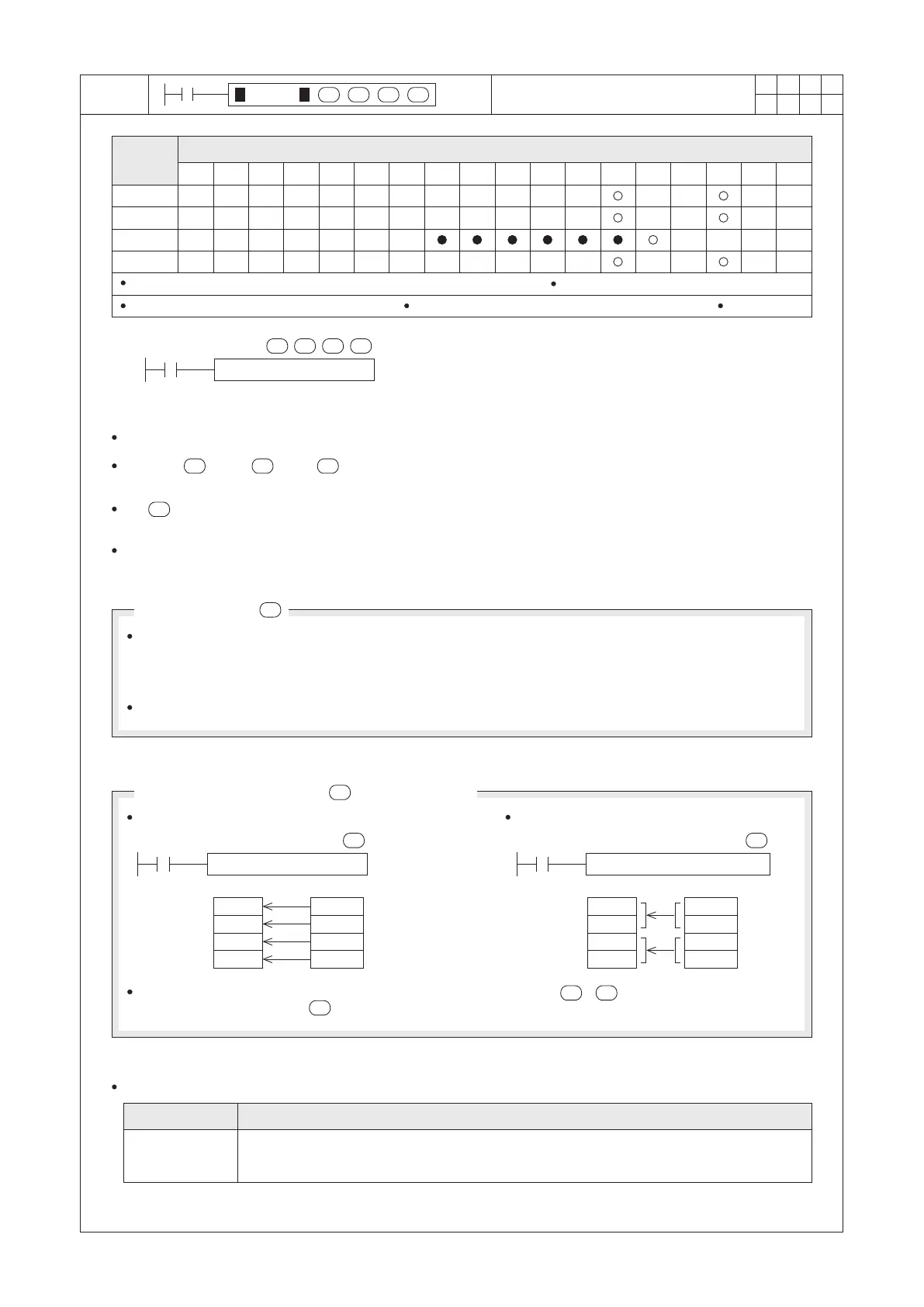
The Main Unit of the VS Series PLC uses this instruction to read BFMs data of the Special Module.
Since the = K2, = K5, = K4 and when X20=“ON”, 4 word data at the BFM #5~BFM #8 in the
specied No. 2 Special Module will be read and store into D0~D3.
The is to appoint a Special Module, the available number is from K1 to K16. For the Main Unit, K1 represents
to access the closest Special Module, and so on.
When X20 is “OFF”, the instruction will not be performed but the data which had read previously will still remain.
D100
D101
D102
D103
BFM #4
BFM #5
BFM #6
BFM #7
DFROM K1 K4 D100 K2
D0
D1
D2
D3
BFM #0
BFM #1
BFM #2
BFM #3
FROM K1 K0 D0 K4
The Number of Data Groups to be Transferred
n
The BFM Number
m2
n
n n
The related special device for this instruction:
M9028
The VS series Special Module has the components of BFMs (Buffer Memory) which are used to store the
setting values and various operation statuses about the module. Each BFM is a 16-bit space. The different
type of special module has a different number of BFM registers. The ID number of BFM registers is coded in
a decimal method, such as #0, #1,.... #9, #10,...
If a Main Unit is through the BFM to manage the module, this module is called the Special Module.
The 16-bit instruction The 32-bit instruction
The number of the data groups to be transferred is determined by the . = 4 in the 16-bit instruction
has the same meaning with = 2 in the 32-bit instruction.
n
n
Relay ID No.
Description
Preventing to operate the FROM/TO repeatedly.
When M9028 is “OFF”, disallows interrupt during FROM/TO is in operation.
When M9028 is “ON”, FROM/TO in an interrupt subroutine is ineffective.
 Loading...