294
S1
S2 S 3
S
D
T C M P P
1
2
M
3
○○
FNC
160
○○
X Y M S
D.b R.b
KnX KnY
KnM KnS
T C
D,R
V,Z
UnG
K,H
E
" $"
S
S1
D
S2
S3
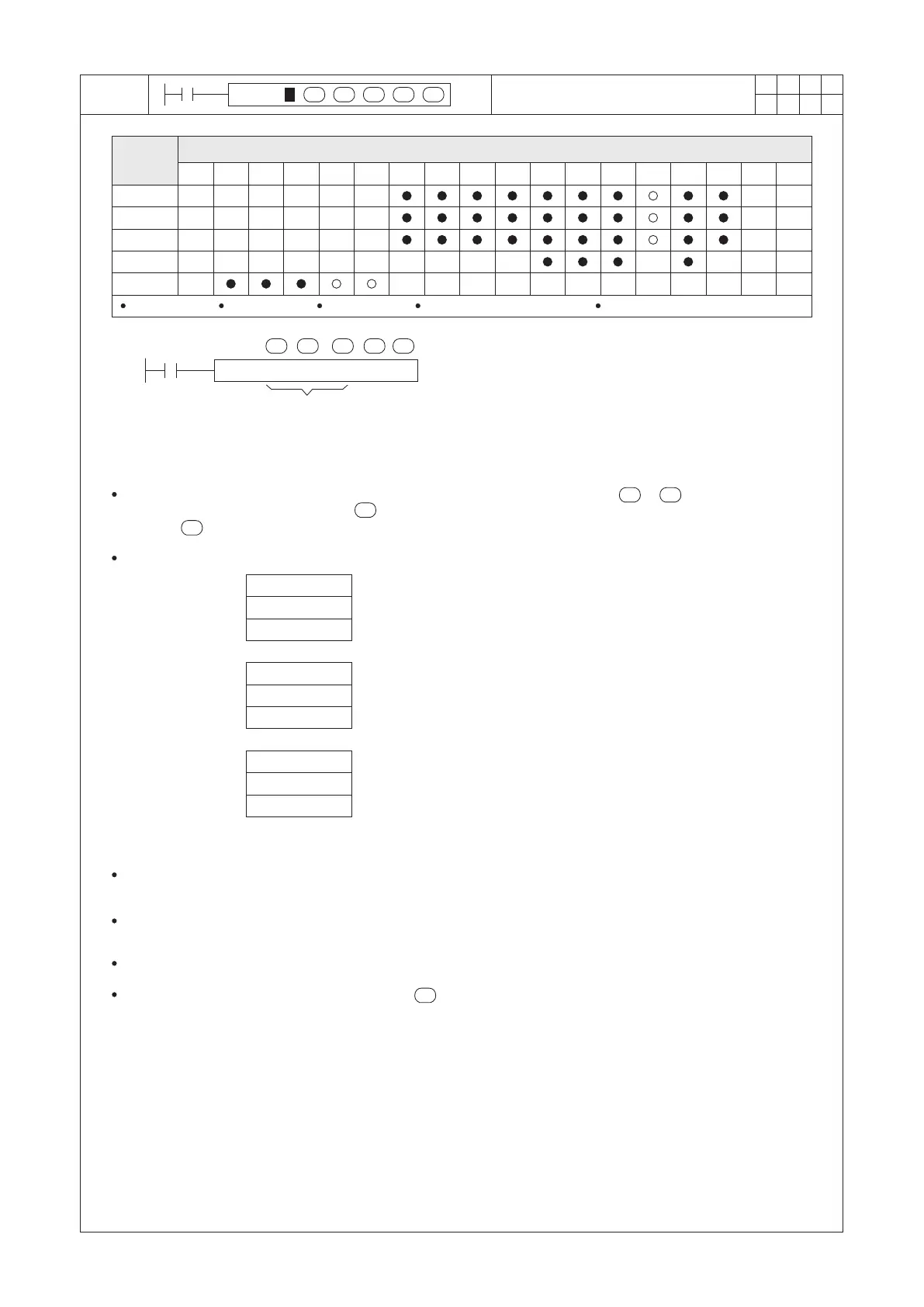
TCMP K8 K30 K20 D0 M0
X20
h m s
08 30 20
D0 (Hour)
D1 (Minute)
D2 (Second)
S1
S2
S
D
S3
S1 S 3
S
D
S
S occupies 3 components D occupies 3 components
S1=0~23 S2=0~59 S3=0~59
Operand
Devices
Time Compare
S1 : the “Hour” for comparison
S2 : the “Minute” for comparison
S3 : the “Second” for comparison
S : the registers of the time combination to do the
comparison
D : the compare result; occupying 3 consecutive
points
Compare the setting value (Hours, Minutes and Seconds which are designated by ~ ) to the time
combination (specied by the head ID of 3 consecutive data devices), and the result of the comparison is
stored to .
When X20 = “ON”, the instruction will be performed.
D0 (Hour)
D1 (Minute)
D2 (Second)
D0 (Hour)
D1 (Minute)
D2 (Second)
h m s
If 08 30 20 >
h m s
If 08 30 20 =
h m s
If 08 30 20 <
, then M0 = “ON”
, then M1 = “ON”
, then M2 = “ON”
The current time of the real time clock is stored in Special Registers D9013~D9015.
D9015 (Hours), D9014 (Minutes), D9013 (Seconds)
When X20 = “OFF”, the instruction is disabled, the “ON”/“OFF” status of M0, M1 and M2 remains the same as the
status before X20 = “OFF”.
Please use serial or parallel links of M0~M2 to generate the result as “≥”, “≤” or “≠”.
If the content value of the register designated by exceeding the time value required, the PLC will regard that as
an operational error.


 To Next Page