295
T Z C P P
S1
S2
D
S
1
2
M
3
○○
FNC
161
○○
X Y M S
D.b R.b
KnX KnY
KnM KnS
T C
D,R
V,Z
UnG
K,H
E
" $"
S
S1
D
S2
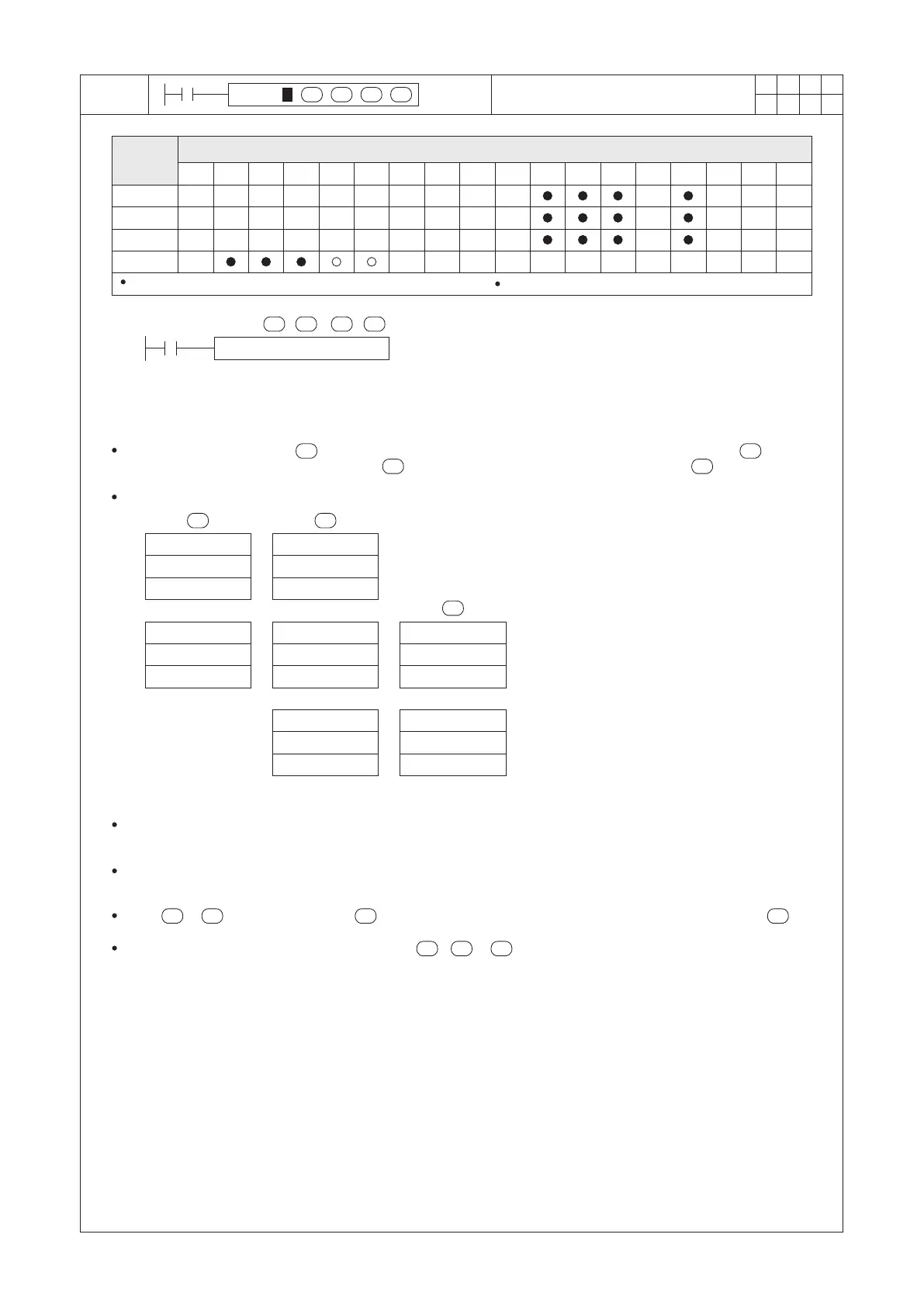
TZCP D0 D10 D20 M0
X20
>
≦
≦
S2
S1S
D
S1
S
S2
S1
S2
S1
S1
S2
S
S1
S2
S
D
>
S1 ≦ S2
Operand
Devices
Time Zone Compare
D0 (Hour)
D1 (Minute)
D2 (Second)
D0 (Hour)
D1 (Minute)
D2 (Second)
D20 (Hour)
D21 (Minute)
D22 (Second)
D20 (Hour)
D21 (Minute)
D22 (Second)
D20 (Hour)
D21 (Minute)
D22 (Second)
D10 (Hour)
D11 (Minute)
D12 (Second)
D10 (Hour)
D11 (Minute)
D12 (Second)
, then M0 = “ON”
, then M1 = “ON”
, then M2 = “ON”
All the S1, S2, S and D occupies 3 components respectively
S1 : the lower setting of the time period combination
S2 : the upper setting of the time period combination
S : the registers of the time combination to do the
comparison
D : the compare result; occupying 3 consecutive
points
The time value is dened by , it will be compared to the lower setting of the time period dened by and the
upper setting of the time period dened by . And then, the compare result will be stored in .
When X20 = “ON”, the instruction will be performed.
S
The current time of the real time clock is stored in Special Registers D9013~D9015.
D9015 (Hours), D9014 (Minutes), D9013 (Seconds)
When X20 = “OFF”, the instruction is disabled, the “ON”/“OFF” status of M0, M1 and M2 remains the same as the
status before X20 = “OFF”.
When > , the content value of will become both upper/lower settings to be compared with the .
If the content value of the register designated by , or exceeding the time value required, the PLC will
regard that as an operational error.
 Loading...