314
1
2
M
3
○○○○
FNC
188
C R C P
n
S
D
X Y M S
D.b R.b
KnX KnY
KnM KnS
T C
D,R
V,Z
UnG
K,H
E
" $"
n
S
D
n = 1〜 256
When S or D is designated to the Kn X, Kn Y, Kn M or Kn S, that Kn has to be K4
CRC D0 D100 K7
X20
S
D
n
S
n
D
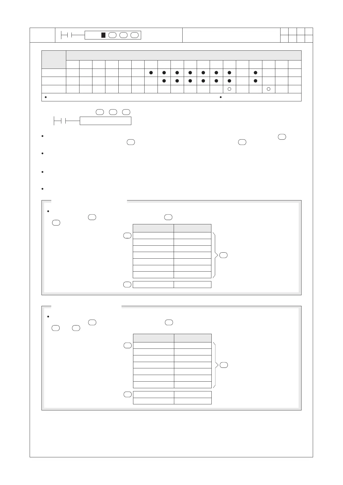
M9161 = “OFF” (16-bit mode)
M9161 = “ON” (8-bit mode)
n
This mode will separate the Upper 8 bits and Lower 8 bits of each 16-bit device as two 8-bit data. The
instruction uses (= K7) 8-bit data (headed by ) to calculate the CRC-16 code and stores the result to
(by a 16-bit value).
S
This mode will take the Lower 8 bits of each device as an 8-bit data (while ignore the Upper 8 bits). The
instruction uses (= K7) 8-bit data (headed by ) to calculate the CRC-16 code and stores the result to
and +1 (by two 8-bit values).
S
n
D D
D100
H01
H03
H04
HED
H85
HA3
H28
H58A6
S
D
n
=K7
D100
D101
H01
H03
H04
HED
H85
HA3
H28
HA6
H58
D
S
n
=K7
D
Cyclic Redundancy Check - 16
Operand
Devices
S : the head ID of continuous data source
D : the device where the result of CRC is stored
n : the number of source data to be checked
This instruction calculates the CRC-16 (Cyclic Redundancy Check) code from the content of continuous bytes
(by the unit of 8-bit) data headed by , the result is stored in the designated device .
When the instruction is used for communication, the CRC-16 is applied to ensure and check the accuracy of the
16 15 2
data transmission. The polynomial of the CRC-16 code: X +X +X +1.
When X20 = “ON”, it uses 7 consecutive 8-bit of data that headed by the D0 to calculate the CRC-16 code, and
the result is stored in the D100 (if the M9161 = “ON”, two 8-bit codes are stored in D100 and D101).
The instruction has two operation modes depending on the status of M9161:
Device
Content value
D0 Lower 8 bits
D0 Upper 8 bits
D1 Lower 8 bits
D1 Upper 8 bits
D2 Lower 8 bits
D2 Upper 8 bits
D3 Lower 8 bits
Device
Content value
D0 Lower 8 bits
D1 Lower 8 bits
D2 Lower 8 bits
D3 Lower 8 bits
D4 Lower 8 bits
D5 Lower 8 bits
D6 Lower 8 bits
 Loading...