324
D PV A L
D1
D2
S
1
2
M
3
○
FNC
201
X Y M S
D.b R.b
KnX KnY
KnM KnS
T C
D,R
V,Z
UnG
K,H
E
" $"
D1
D2
S
2DH( –) 20H( ) 31H( 1) 32H(2) 33H(3) 34H( 4) 35H(5)
00H
S
2EH(•)
–123451
2
3
–
4
5
D20
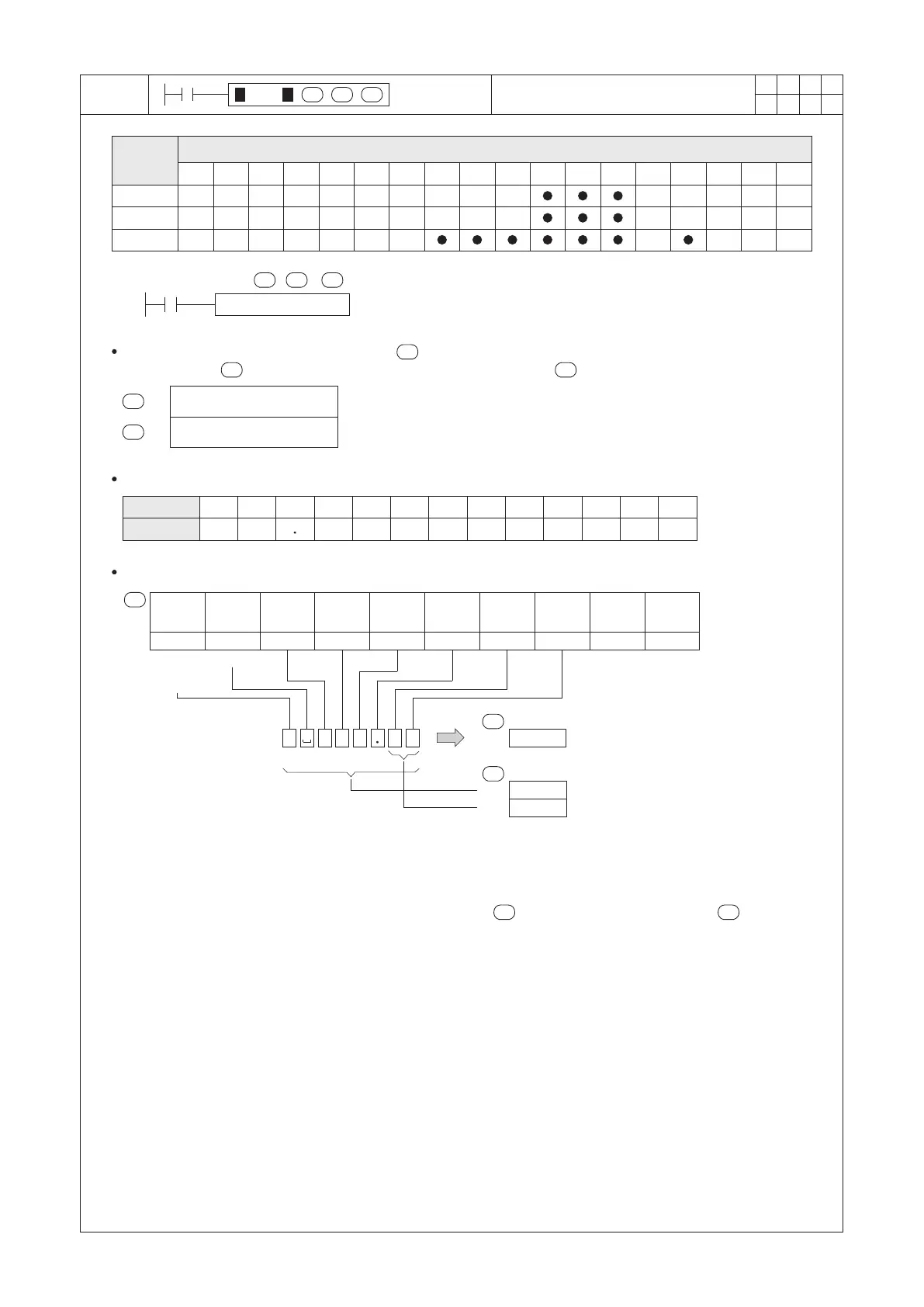
S : the head ID of the devices where character string is stored
D1 : the format of the character string
D2 : the converted BIN number result
VAL D0 D10 D20
X0
This instruction uses a string started from the to perform the BIN number conversion, then stores that format
into the devices and the results of BIN pure number into the device .
S
S
When X0 = “ON”, the 16-bit instruction will be executed as follows:
D2
D1 D2
D1
D1
+1
D1
D2
D10
D11
8
2
D1
The positive or negative sign: the 20H represents positive; the 2DH represents negative.
After the conversion, will get the BIN pure number part at (-12345) and the string format at .
D2 D1
Operand
Devices
Character String to BIN Conversion
Length of the converted string
Number of digits after the decimal point
Length of the converted string
Number of digits after the
decimal point at the string
16-bit instruction, the length = 2~8; 32-bit instruction, the length = 2~13.
16-bit instruction, the digits = 0~5; 32-bit instruction, the digits = 0~10.
0
1
2
3
4
5
6
7
SPACE
–
8
9
30H 31H 32H 33H 34H 35H 36H 37H 20H
2DH 2EH
38H 39H
This instruction will use the following ASCII conversion table:
Sign & Number
ASCII Cord
Positive or
negative
sign
Space
End of
string
D0
Lower
8 bits
D0
Upper
8 bits
D1
Lower
8 bits
D1
Upper
8 bits
D2
Lower
8 bits
D2
Upper
8 bits
D3
Lower
8 bits
D3
Upper
8 bits
D4
Lower
8 bits
D4
Upper
8 bits
The byte next to the positive or negative sign is a blank space, that should ll in the code 20H.
 Loading...