392
C P U L
S1
S2
n
S2S1
n
1
2
M
3
○○○○
FNC
87
X Y M S
D.b R.b
KnX KnY
KnM KnS
T C
D,R
V,Z
UnG
K,H
E
" $"
S1
S2
n
CPUL DISTRIBUTED_CTRL D100 K1
X20
S1
RS- 485RS- 232
Operand
Devices
CPU Link Communication Instruction
Using a Table Code Q0~Q31 (V, Z index modiable) or a Table Nickname (by user-dened 16 English characters)
S2 occupies 4 components
For the VS1 series, n1=1~2; for the VS2 or VSM series, n1=1~3; for the VS3 series, n1=1~5
S1 : the communication table that describes the data
receiving and transmitting
S2 : the working area for the instruction that occupies
4 registers
n : to designate the communication port, 1~5 =
CP1~CP5
The VS Series PLC uses this instruction to share the particular data via its Communication Port CP1~CP5 with
other VS PLCs, that achieved the purpose of distributed control.
The main character of the CPU LINK is to share instant data.
What we call “Instant” means all the communication work is dealt with instantly without being affected by the PLC
scan time. Other communication method, such as Easy LINK, MODBUS communication and Non Protocol
communication, will follow the PLC's executive cycle and thus is affected by the PLC scan time.
What we call “share” means the way of the CPU LINK communication work is that each station in the
communication network automatically transfers a part of data orderly to other stations in the network. This way the
operation of the whole communication network can be understood through each station in the communication
network.
Through the function of CPU LINK that instantly sharing data with other PLCs, a distributed control system can be
established.
The CP1~CP5 are multi-functional communication ports. Each port can choose an appropriate communication
type from its various functions. When this instruction is using a port, should choose the “Application type:” become
the “CPU Link”. Regarding the application type selection and related parameter setting, please specify it from the
programming software Ladder Master S and at the “Project” -- “COM Port Setting”.
This instruction could be used to transfer for various devices that is including all the Y, M, S, T, C, D and R (except
for special M and special D).
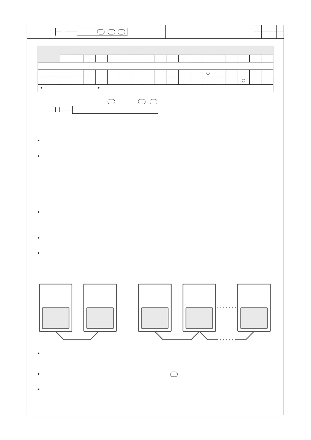
As shown in the gure below, rst use the Ladder Master S to orderly open every PLC's project and set its
“Application type:”as the “CPU Link” then to set an unique station No. (ranging from 0~254) hereafter connect to
the programming port of every PLC to load the project to each PLC.
Afterward, write this instruction in one of the PLC's program then edit the CPUL communication table to designate
data sharing actions, hereafter to load this project to the specic PLC. Following these procedures, the purpose of
sharing instant data between the PLCs is reached.
VS series
PLC
CPU LINK
St. #1
VS series
PLC
VS series
PLC
VS series
PLC
VS series
PLC
CPU LINK
St. #2
CPU LINK
St. #1
CPU LINK
St. #2
CPU LINK
St. #n
When X20 = “ON”, the CPUL instruction starts execution. According to the contents described in the
“DISTRIBUTED_CTRL” communication table, it will arrange sharing particular data between stations, while the
D100~D103 will be occupied to store the state of instruction execution.
When the contents of the communication table specied by the are execution completed from beginning to
end, it will start over again from the rst item set of the table.
When the X20 turns from “ON” to “OFF”, this instruction stops and the data sharing immediately stop but data
which has transferred previously will still remain.