393
The communication table is assigned by the of the instruction.
An example of the “CPU Link” provided by programming tool the Ladder Master S is shown below.
S1
The working area of the executive instruction is starting from the (using D100~D103 as the example).
S2
D100
D101
D103
〜
Description
S2
1
2
3
4
0
D0 – D9
D10 – D19
D20 – D29
D30 – D39
M1
M1
M2
1
2
3
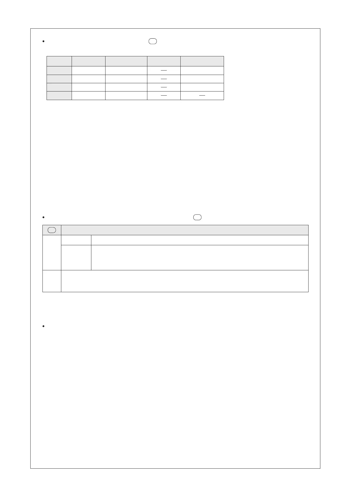
Item No.
Station No.
Device Range
Word/Bit Disable Contact
※ When the device is selected to be the bit device (Y, M, S or the contact of T, C), the initially ID number at the
device range must be a multiplier of 8, such as Y0, Y10, Y20, M0, M24 or T8. Also, the length must be a
multiplier of 8 as well, such as M0~M23 (24 devices), T8~T15 (8 devices), Y10~Y27 (16 devices), M24~M63
(40 devices).
The rst item set in the table means that Station #0 transmits its D0~D9 to the D0~D9 of other stations in the
communication network.
The second item set in the table means that Station #1 transmits its D10~D19 to the D10~D19 of other stations in
the communication network.
The third item set in the table means that Station #2 transmits its D20~D29 to the D20~D29 of other stations in the
communication network.
The fourth item set in the table means that Station #3 transmits its D30~D39 to the D30~D39 of other stations in
the communication network.
The last column of the table is for the Disable Contact. If that specied contact is “ON”, the communication item
set will be ignored. For example, if M1 = “ON”, the rst and second item sets in the table will skip. This is the new
function of the VS series, which can help designers effectively manage the operation of the communication table.
A communication item set does not need to specify a Disabled Contact (such as the fourth item set), so that the
command of the set does not have the disable control function.
The working area is required for the system when this instruction is performed
If any communication error occurs during the execution of the instruction, a code will be recorded in D100. Only
when the content value of D100 is 0, the recording action can be executed.
Therefor, when there are possibilities of several errors, users can use the program to move out the content value of
D100 then reset it to 0. This way allows the D100 to record the next error.
To edit a communication table
Use the Ladder Master S to set up a CPUL communication table and through its interactive window can set up and
edit a communication table easily.
In the structure of VS Series PLC, the communication tables are a part of the project. When the programmer to copy
or access the project, those tables will be duplicated automatically with the program.
Lower 8 bits
The record of the station number when the rst communication error is occurred
Upper 8 bits
Instruction working status
0: Normal data transmitting / receiving
A: The communication setting is normal but no response from the Slave station (Time-out occurs)
B: Abnormal communication

 Loading...