400
1
Reset by program
The Related Flags and Data Registers
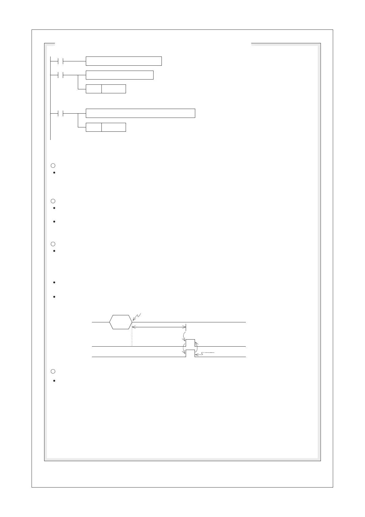
Fill the data string to be sent
Move the received data to the data storage area
Reset the data receive
completed flag
Edit the data string which is beginning from the D0 to be sent and the
length of data string is specified by the D200.
The M9100 will turn “OFF” automatically when that data sending out is completed.
Do not use the RST instruction to reset the M9100.
Move the received data string which is beginning from
the D100 to the data storage area.
Reset the data receive completed flag M9101 for preparing to receive the next data
string set. Do not reset the M9101 consecutively in the program.
RS D0 D200 D100 D201 K1
SET
RST
M9100
M9101
X20
M9101
Set the data sending
out request flag once
Sequence of Data Sending and Receiving (Using the CP1 as an example)
2
3
Data
Receiving data
Receiving data
The time-out duration
M9102
M9101
4
A trigger
pulse for
to send
data
The data
receiving is
completed
The Data Sending Out Flag M9100:
When the conditional contact X20 = “ON”, the RS instruction is performed. At this time, if a pulse signal
forces the status of M9100 to be “ON”, the content values of the registers which are beginning from D0
will be sent out via the serial communication port CP1. After the data sending is completed, the M9100
will be reset to “OFF” automatically.
The Receive Completed Flag M9101:
When the conditional contact X20 = “ON”, the RS instruction is performed. The CP1 of PLC is ready to
receive communication data.
When the data receiving is completed, the M9101 = “ON”. At this moment, the received data in the buffer
should be moved to the data storage area, and then M9101 could be reset to “OFF”. Afterwards, PLC will
be ready for the status of receiving immediately.
The Receive Time-out Flag M9102:
When the data of receiving is paused and the waiting time exceeds the Time-out duration (designated by the
“COM Port Setting”), the M9102 will turn “ON” to represent the happening of Time-out also the Receive
Completed ag M9101 will be forced “ON” to terminate the data receiving action.
The M9102 will not reset automatically, must use an instruction in the program to reset the status of M9101
then the M9102 will be reset too.
By using the function of the Time-out ag, the PLC could receive the data of transferring from peripheral
equipments which without the particular length or “End of Text”.
The Time-out duration is specied by using the programming software Ladder Master S – “Project” –
“COM Port Setting”.
The Communication Abnormal Flag M9103:
When the RS instruction occurs Parity error or Framing error, the Communication Abnormal Flag M9103
will turn ON. The M9103 must use an instruction in the program to reset the status of M9103
 Loading...