403
Non Protocol
Baud Rate: 19200 bps
CP1 CP1
VS Computer Link Slave
Baud Rate: 19200 bps
Station No.: #1
00H
+
07H
+
00H
+
20H
+ + + + + +
A0H 34H 12H 00H 05H 00H
=
112H
D
L
E
S
T
X
10H 02H 20H00H
D
L
E
E
T
X
10H 03H
07H 00H A0H 34H 12H 00H 05H 00H 31H 32H
L H
〜
L H L H H L
D
L
E
S
T
X
10H 02H 20H01H
D
L
E
E
T
X
10H 03H07H 00H A0H 01H 00H 00H 01H 00H 43H
41H
L H
〜
L H L H H L
D
L
E
A
C
K
10H 06H 00H
D
L
E
E
T
X
10H 03H
Content
value
of D1
01H 03H 00H 00H
00H 30H 34H
L H L H H L
D
L
E
S
T
X
10H 02H 28H01H
D
L
E
E
T
X
10H 03H09H 00H A0H 00H 00H 00H 01H 00H 44H 33H
L H
〜
L H L H H L
D
L
E
A
C
K
10H 06H 00H
D
L
E
E
T
X
10H 03H
01H 01H 00H 30H 32H
L H H L
Data write
to D0
00H 00H
L H
The command
data string is sent
to the Slave
Station #1
The feedback data
string from the
Slave Station #1
The command
data string is sent
to the Slave
Station #1
The feedback data
string from the
Slave Station #1
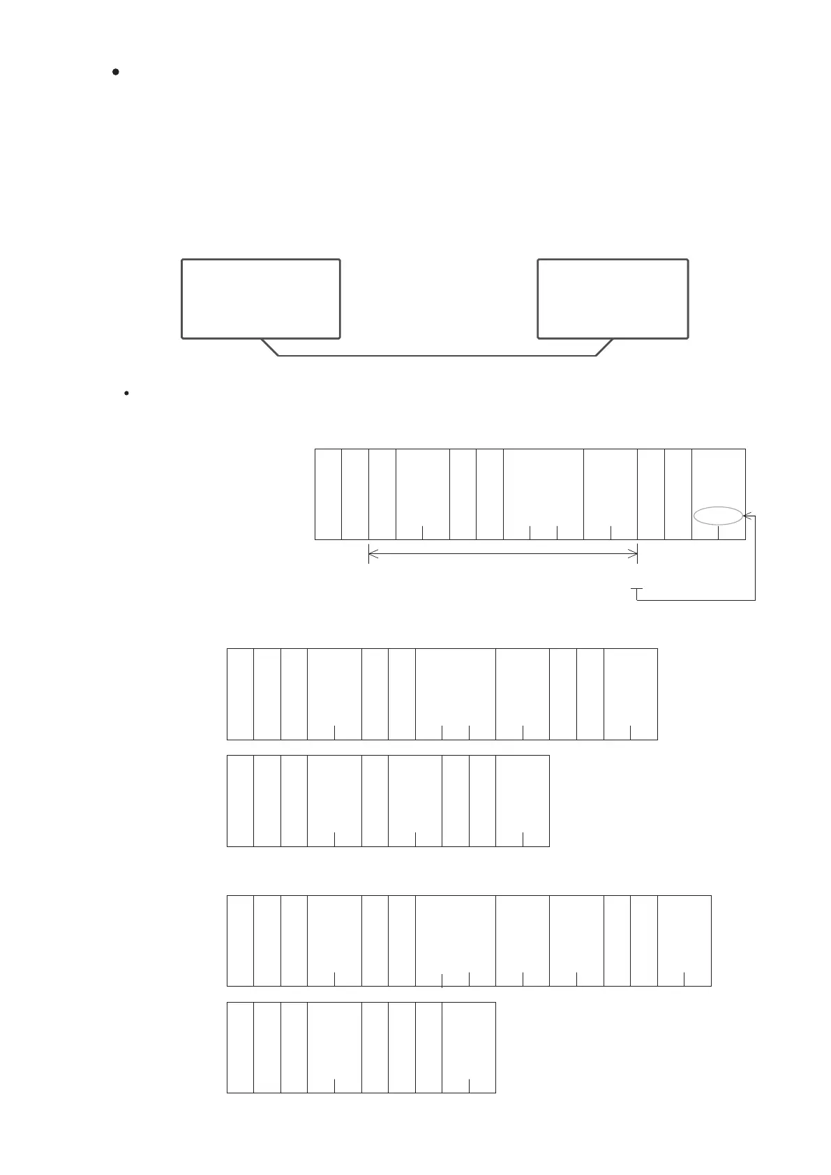
Application Example
Master VS PLC Slave VS PLC #1
In this example, two VS PLC’s CP1 are connected by the RS-485 interface and execute the Non Protocol
communication.
In the following gure, let the left one executes the “Non Protocol” application type and set the baud rate to be 19200
bps.
Let the right one executes the “VS Computer Link Slave” application type. The baud rate should be the same as the
port of the left PLC also set the station number become the Slave #1.
Afterward, edit a relevant communication program and write that into the left PLC. The program uses the RS
instruction and follows the “VS Compurter Link Protocol” (hereby referred to as VS Protocol) format to access the
right side PLC's data.
Actually, there are simpler ways to exchange data between VS Series PLC’s in the real applications. This main purpose
of this example is to demonstrate the usage of the “Non Protocol” and the RS instruction.
The application example below briey explains the relevant descriptions to the “VS Protocol”. For the details about
the protocol, please refer to the section “7-4 VS Series PLC Communication Protocol”.
The parameters of the VS Protocol are --- bits-per-character: 8 bits ; parity check: NONE ; stop bit: 1bit.
The rule of the SUM Check code:
Sum up the content values of data
from the beginning of the station No.
to the end of the data block.
Convert the last two digits of the
total HEX value into two ASCII
codes to be the SUM Check code.
Both the data sending and receiving
devices should operate the same
code-checking procedures that can
ensure the data transmission to be correct.
Sum up those HEX values and store at the last 2 digits by the ASCII codes
Station
No.
The communication command is to read the content value of the D1 from the Slave Station #1. (Assume the content
value of the D1 is 0000H)
The communication command to write a value into the D0 in the Slave Station #1. (Assume the data to be written is 0000H)
Station
No.
Station
No.
Station
No.
Station
No.
Number
of data
Bytes
Number
of data
Bytes
Number
of data
Bytes
Number
of data
Bytes
Number
of data
Bytes
Head number
of devices
Function
code
SUM
Check
Device
code
Number
of
devices
SUM
Check
SUM
Check
Number
of
devices
Head number
of devices
Head number
of devices
Device
code
Device
code
Function
code
Function
code
SUM
Check
SUM
Check
Number
of
devices
Error code
Error code
 Loading...