402
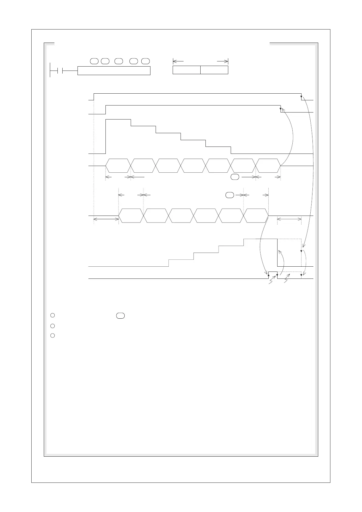
RS D0 K5 D100 K10 K1
X20
4
3
2
1
5
0
4
3
2
1
0
S
m
D
n
n1
Useless
The Lower 8 bits of the 16-bit
data is treated as one Byte data.
(the Upper 8 bits data are useless)
Description of Data Sending / Receiving (by the CP1): 8-bit Mode (M9161 = "ON")
A 16-bit data
Lower 8 bits
D9101 the number
of data remaining
to be transferred
Data sending out
(TXD)
PLC→Peripheral
Data received
(RXD)
PLC ← Peripheral
Conditional contact
X20 to active the
instruction
Data sending out
request ag M9100
D9102 the number
of received data
The data receive
completed ag M9101
STX
ETX
D0
Lower 8 Bits
D1
Lower 8 Bits
D2
Lower 8 Bits
D3
Lower 8 Bits
D4
Lower 8 Bits
End
of Text
Number of sending out data Bytes is designated by
m
Start
of Text
End
of Text
Start
of Text
Ready for
receiving
STX
ETX
Ready for
receiving
Reset by the program
Not reset by the
program
D100
Lower 8 Bits
D101
Lower 8 Bits
D102
Lower 8 Bits
D103
Lower 8 Bits
Either one of the condition below is completed will cause the receive completed ag M9101 “ON” and stop to
receive.
The number of assigned bytes is satised.
The End of Text is received.
The occurrence of Time-out.
1
2
3
n
n
Number of received Bytes is designated by
 Loading...