423
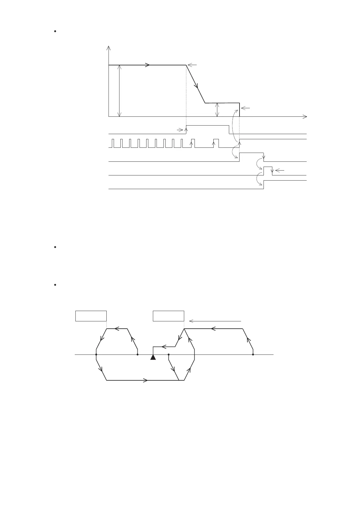
DOG Front End with PG0 count home positioning
1
2
3
Data-set type home return
At this mode, the motor does not rotate because it is no actual moving position. When the function is operated, it
will fill the preset value of the home position into the register which stores the present value also turn the home
positioning complete flag “ON”. If the CLR output is activated, the width of the signal pulse is ≥ 20ms.
Dog search home positioning
When the positioning system has installed with limit switches to provide the limiter signals for the VS PLC, by this
mode that will give the automatic search capability for the home positioning. (the examples are using the DOG
Rear End home positioning)
Limit switch
DOG
Direction of home positioning
Home
( 4) (3) (2) ( 1)
The diagram above illustrates the different actions from the starting points (1)~(4) to complete the home positioning.
(1) If the starting point is located on the right of the DOG switch:
The home positioning is moving the sliding table by the home positioning speed and the direction of home
positioning. Until the Front End of the DOG is reached, the speed decreases to the creep speed, then to finish
the home positioning.
(2) If the starting point had been driving the DOG switch “ON”:
The home positioning is moving the sliding table by the home positioning speed and the opposite direction of
home positioning. Until the Front End of the DOG is separated (the signal turns from “ON” to “OFF”), the speed
slowing down and then stop. After that, it is moving the sliding table by the home positioning speed and the
direction of home positioning. Until the Front End of the DOG is reached, the speed decreases to the creep
speed, then to finish the home positioning.
Starts to count PG0 signals after
DOG’s Front End is appeared.
Set number of PG0 signals = 3.
Speed
Direction of home positioning
Home positioning speed
Home positioning creep speed
DOG Signal
CLR Signal
PG0 Signal
Positioning
completed ag
Home positioning
complete ag
Instantly stops when the PG0’s
counting set value is reached
Time
Condition contact
“OFF”
DOG Front End, start to slow down
The DOG signal may use a X or M. Usually assigned to the X0~X7, because the interrupt input
point can have the instant response.
Should avoid the DOG's Front End signal to be too close to the PG0’s Front End signal, that
may cause the PG0 counting error.
For the PG0 signal input, must use X0~X7. The PLC processes the counting by the way of
interrupt.
The CLR signal output can assign to a Y or M, the width of that “ON” signal is ≥ 20ms.
 Loading...