P
r
o
t
e
c
t
e
d
b
y
c
o
p
y
r
i
g
h
t
.
C
o
p
y
i
n
g
f
o
r
p
r
i
v
a
t
e
o
r
c
o
m
m
e
r
c
i
a
l
p
u
r
p
o
s
e
s
,
i
n
p
a
r
t
o
r
i
n
w
h
o
l
e
,
i
s
n
o
t
p
e
r
m
i
t
t
e
d
u
n
l
e
s
s
a
u
t
h
o
r
i
s
e
d
b
y
V
o
l
k
s
w
a
g
e
n
A
G
.
V
o
l
k
s
w
a
g
e
n
A
G
d
o
e
s
n
o
t
g
u
a
r
a
n
t
e
e
o
r
a
c
c
e
p
t
a
n
y
l
i
a
b
i
l
i
t
y
w
i
t
h
r
e
s
p
e
c
t
t
o
t
h
e
c
o
r
r
e
c
t
n
e
s
s
o
f
i
n
f
o
r
m
a
t
i
o
n
i
n
t
h
i
s
d
o
c
u
m
e
n
t
.
C
o
p
y
r
i
g
h
t
b
y
V
o
l
k
s
w
a
g
e
n
A
G
.
24 – Mixture preparation - injection
1 Injection system
⇒ “1.1 General notes on the injection system”, page 215
⇒ “1.2 Rules for cleanliness”, page 215
⇒ “1.3 Technical data”, page 216
⇒ “1.2 Vacuum hose connection diagram”, page 137
⇒ “1.3 Assembly overview - vacuum hoses”, page 138
1.1 General notes on the injection system
♦ Fuel hoses in engine compartment must be secured only with
spring-type clips which conform to production standard. The
use of crimp-type or screw-type clips is not permissible.
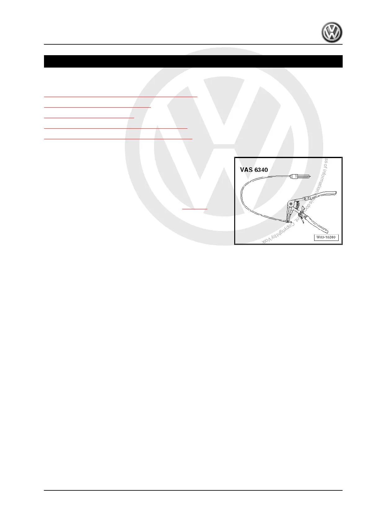
♦ Spring-type clip pliers - VAS 6340- or space saving hose clip
pliers - VAS 6362- are recommended for installing and remov‐
ing spring-type clips.
♦ Note safety precautions before beginning work ⇒ page 1 .
♦ The battery must be disconnected only with ignition switched
off. If a coded radio is installed, ascertain code before discon‐
necting battery.
♦ Observe required procedures after connecting battery ⇒ Elec‐
trical system; Rep. gr. 27 ; Disconnecting and reconnecting
battery.
♦ For trouble-free operation of electrical components, a voltage
of at least 11.5 V is necessary.
♦ Do not use sealants containing silicone. Particles of silicone
drawn into the engine will not be burnt in the engine and dam‐
age the Lambda probe.
♦ If, after fault finding, repairs or component tests, the engine
starts, runs for a short period and then stops, then the fault
may be that the immobilizer is blocking the engine control unit.
In this case, the control unit must be adapted.
♦ Certain tests may lead to an event being detected by the con‐
trol unit and stored. Therefore, after completing all the checks
and repairs, read the event memory and clear it if necessary
⇒ Vehicle diagnostic tester.
♦ Vehicles with an airbag are fitted with a crash fuel shut-off. It
reduces the danger of a fire following a crash as the fuel pump
is switched off via the fuel pump control unit - J538- .
♦ When driver door is opened, fuel pump is activated for 2 sec‐
onds to generate pressure in fuel system. This improves the
quality of the start behaviour.
1.2 Rules for cleanliness
When working on the fuel supply/injection system, pay careful at‐
tention to the following “5 rules”:
♦ Thoroughly clean all joints and surrounding areas before dis‐
mantling.
♦ Place removed parts on a clean surface and cover them over.
Use lint-free cloths only.
♦ Carefully cover opened components or seal them if repairs
cannot be carried out immediately.
Touareg 2010 ➤ , Touareg 2015 ➤
6-cylinder direct-injection engine (3.6 l engine, 4V) - Edition 12.2019
1. Injection system 215