8-30 SHB WL34 * 2.0
8 Hydraulic system
Diagrams
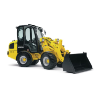
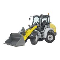
Equipment variant 1: HDM19/3 with HDS15/1
Option:
• Float position
• Load stabilizer
• Lift cylinder with counterbalance valve
• Pressure-free reverse travel/leakage pipe
• 3rd control circuit comfort
• 4th control circuit additionally via tandem pump
• Differential lock
Legend
Item Description
1 Rear machine section
2 Front chassis section
3 4th control circuit, connection for front attachments
4 3rd control circuit, connection for front attachments
5 3rd control circuit right
6 3rd control circuit left
7 Lower
8Raise
9 Unroll
10 Roll up
11 Center joint
12
Engine options:
- 404D-22 (35.7 kW)
- 404F-22 (35.7 kW)
- TD2011 L04W (55.1 kW)
13 Optional 19 ccm / 28 ccm / 22.5 ccm
14 Front-axle drum brake
15 Foot operation
16 To manifold
17 Front axle differential lock
18 Rear axle differential lock
19 Manifold
20 Return without pressure, optional at front or rear
21 Leak oil line